


Installation
33
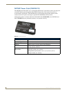
7" Modero Widescreen Touch Panels
Installation
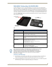
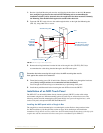
NXT panels are mounted onto flat (horizontal) surfaces in either a stand-alone or combo (NXT atop an
NXA-BASE/1 battery base) configuration. NXD panels are installed into either a pre-wall surface (using
a CB-TP7 rough-in/wallbox) or a solid surface (using either solid surface or drywall screws).
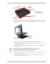
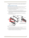
Unpacking the Panel
1. Inspect and confirm the contents of the shipment box to verify you have all specified parts. Refer to
the Specifications for 7" Widescreen Video Touch Panels section on page 3 for more information
about included accessories and other AMX equipment.
2. Carefully remove the panel from the shipping box.
3. Carefully peel the protective plastic cover from the LCD.
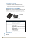
Installing the Internal Components
Installation of the internal components such as the upgraded Compact Flash Memory card and the
NXA-WC80211GCF Wireless card are described in detail within the following sections:
NXA-WC80211GCF 802.11g Wireless Card (FG2255-07) section on page 15.
NXA-CFSP Compact Flash (FG2116-3x) section on page 18.
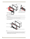
Installing the No-Button Trim Ring
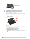
The NXD-CV7 panel is shipped from AMX with the default Button Trim Ring already installed. The
unit is also shipped with an included Trim Ring containing no button openings (a No-Button Trim Ring)
that allows you, if desired, to change the default configuration of the NXD panel Faceplate to that with
no-button openings. In order to install this included No-Button Trim Ring, you must first remove the
factory-installed default Button Trim Ring, the six small buttons, and associated two clear light pipes.
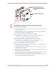
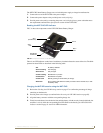
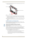
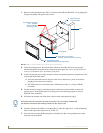
1. The Faceplate is secured to the panel with plastic latches. To remove the Faceplate, simply pull it
away from the panel by gently tugging it outwards until the entire Faceplate comes away from the
panel.
2. Turn the Faceplate over to expose the inside surface and view the Trim Ring latches (FIG. 32).
3. In a single motion, press down and then outwards on the three Trim Ring latches located along the
top of the internal surface of the Faceplate to begin removing the Button Trim Ring. Removing the
Internal Faceplate from the panel exposes the pushbuttons and light pipes along the inside of the
Internal Faceplate.
4. Gently tug along the edges of the Button Trim Ring and work your way around the edges to remove
it from the Faceplate (FIG. 32).
5. From along the internal surface of the Faceplate, remove the six buttons by gently bending each
Button latch up and pulling the button outwards.
It is recommended that if you are planning on upgrading your panel components
(flash and wireless), you do so before beginning any panel installations.
If the protective plastic LCD cover is not removed, the panel may not respond
properly to touch points on the LCD or allow proper screen calibration.