


Installation
38
7" Modero Widescreen Touch Panels
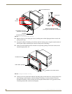
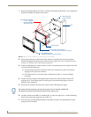
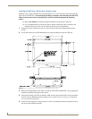
1. Remove the Faceplate/bezel (A in FIG. 37) from the main NXD unit (B in FIG. 37) by gripping the
faceplate and pulling with gentle outward force.
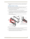
2. Verify the incoming power, RJ-45 audio/video, Ethernet, and USB cables have been properly
threaded through the wiring knockouts on the left of the rough-in box. Leave enough slack in the
wiring to accommodate any re-positioning of the panel.
3. Connect all data and power wiring connectors to their corresponding locations along the side of the
(un-powered) NXD touch panel.
Verify that the terminal end of the power cable is not connected to a power source before
plugging in the 2-pin power connector.
The USB connectors can be from either a USB extension cable, or a wireless USB RF
transmitter.
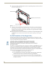
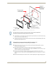
4. Test the incoming wiring by connecting the panel connections to their terminal locations and
applying power. Verify that the panel is receiving power and functioning properly to prevent
repetition of the installation.
5. Disconnect the terminal end of the power cable from the connected power supply.
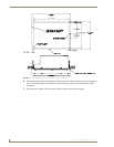
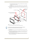
6. Carefully slide the main NXD-CV7 unit (B in FIG. 37) into the rough-in box, so that all Mounting
Tabs lie flush against the rough-in box (C in FIG. 37).
7. Insert and secure four #4-40 Mounting Screws (included) into their corresponding holes located
along the sides of the NXD.
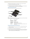
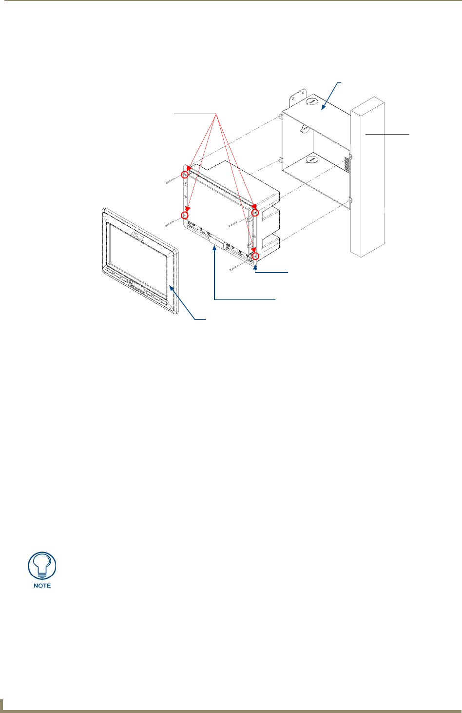
FIG. 37 NXD-CV7 panel installation into a CB-TP7 (pre-wall construction)
B - Main NXD unit consists of
C - Optional CB-TP7
#4-40 Mounting Screws
(four - included)
secure the NXD to
Stud
the touch panel and back box housing
rough-in/wallbox
A - Faceplate/Trim Ring
default Faceplate comes with buttons
the Rough-In Box
Mounting Tab
Don’t disconnect the connectors from the touch panel. The unit must be installed with
the attached connectors before being inserted into the rough-in box.