


Installation
39
7" Modero Widescreen Touch Panels
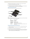
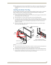
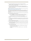
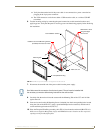
8. Place the Faceplate/Trim Ring assembly (A in FIG. 37) back onto the main NXD unit
(B in FIG. 37). Make sure to align the Microphone, Light, and PIR Motion sensor locations to their
respective openings on the front faceplate/bezel.
9. Reconnect the terminal RJ-45, Ethernet, USB, and any optional audio/video wiring to their
respective locations (outside the rough-in box) on either the NXA-AVB/ETHERNET Breakout Box,
Ethernet port, or NetLinx Master.
10. Reconnect the terminal power connector on the 12 VDC-compliant power supply and apply power.
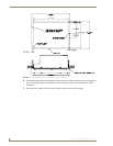
Installing the NXD into drywall using Expansion Clips
Expansion clips are mounted through the three oval holes located along the rim of the NXD-CV7. As the
screw is tightened, the clip bends toward the insertion hole and into the wall. This bending creates a
"grip" on the wall by either pressing onto the wall or by securing the drywall between the housing and
the drywall clip.
The most important thing to remember when mounting the NXD is that the outer frame (Mounting Tabs)
must be installed flush against the mounting surface.
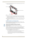
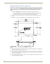
Refer to SP-2258-01 for detailed installation dimensions (reproduced in FIG. 38).
It is recommended that you cutout the surface slightly smaller than what is outlined in the
installation drawings so that you can make any necessary cutout adjustments.
1. Prepare the area by removing any screws or nails from the drywall before beginning the cutout
process.
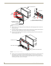
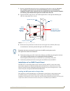
2. Cut out the surface for the NXD Wall Mount unit using the dimensions shown in FIG. 38. Be sure to
cut out the three notches along the sides to accommodate the three corresponding drywall expansion
clips (included).
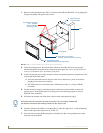
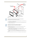
3. Remove the Faceplate/bezel (A in FIG. 39) from the main NXD unit (B in FIG. 39) by gripping the
faceplate and pulling with gentle outward force.
4. Thread the incoming power, RJ-45, Ethernet, USB, and any optional audio/video wiring (from their
terminal locations) through the surface opening. Leave enough slack in the wiring to accommodate
any re-positioning of the panel.
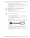
5. Connect all data and power wiring connectors to their corresponding locations along the left side of
the (un-powered) NXD touch panel.
Verify that the terminal end of the power cable is not connected to a power source before
plugging in the 2-pin power connector.
The USB connectors can be from a either a USB extension cable, or a wireless USB RF
transmitter.