


Upgrading Modero Firmware
83
7" Modero Widescreen Touch Panels
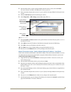
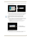
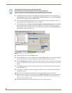
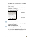
6. Click the Edit Settings button (on the Communications Settings dialog) to open the Virtual NetLinx
Master Settings dialog (FIG. 77).
7. From within this dialog enter the System number (default is 1).
8. Click OK three times to close the open dialogs, save your settings, and return to the main NetLinx
Studio application.
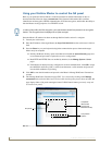
9. Click the OnLine Tree tab in the Workspace window to view the devices on the Virtual System. The
default System value is one.
10. Right-click on the Empty Device Tree/System entry and select Refresh System to re-populate the
list.
The panel will not appear as a device below the virtual system number (in the Online Tree tab)
until both the system number used in step 7 for the Virtual NetLinx Master (VNM) is entered into
the Master Connection section of the System Settings page and the panel is restarted.
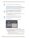
Step 3: Confirm and Upgrade the firmware via the USB port
Use the CC-USB Type-A to Mini-B 5-wire programming cable (FG10-5965) to provide communication
between the mini-USB Program port on the touch panel and the PC. This method of communication is
used to transfer firmware Kit files and TPD4 touch panel files.
1. Verify this direct USB connection (Type-A on the panel to mini-USB on the panel) is configured
properly using the steps outlined in the previous two sections.
2. With the panel already configured for USB communication and the Virtual Master setup within
NetLinx Studio, its now time to verify the panel is ready to receive files.
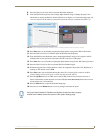
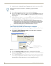
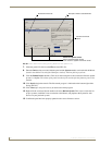
3. After the Communication Verification dialog window verifies active communication between the
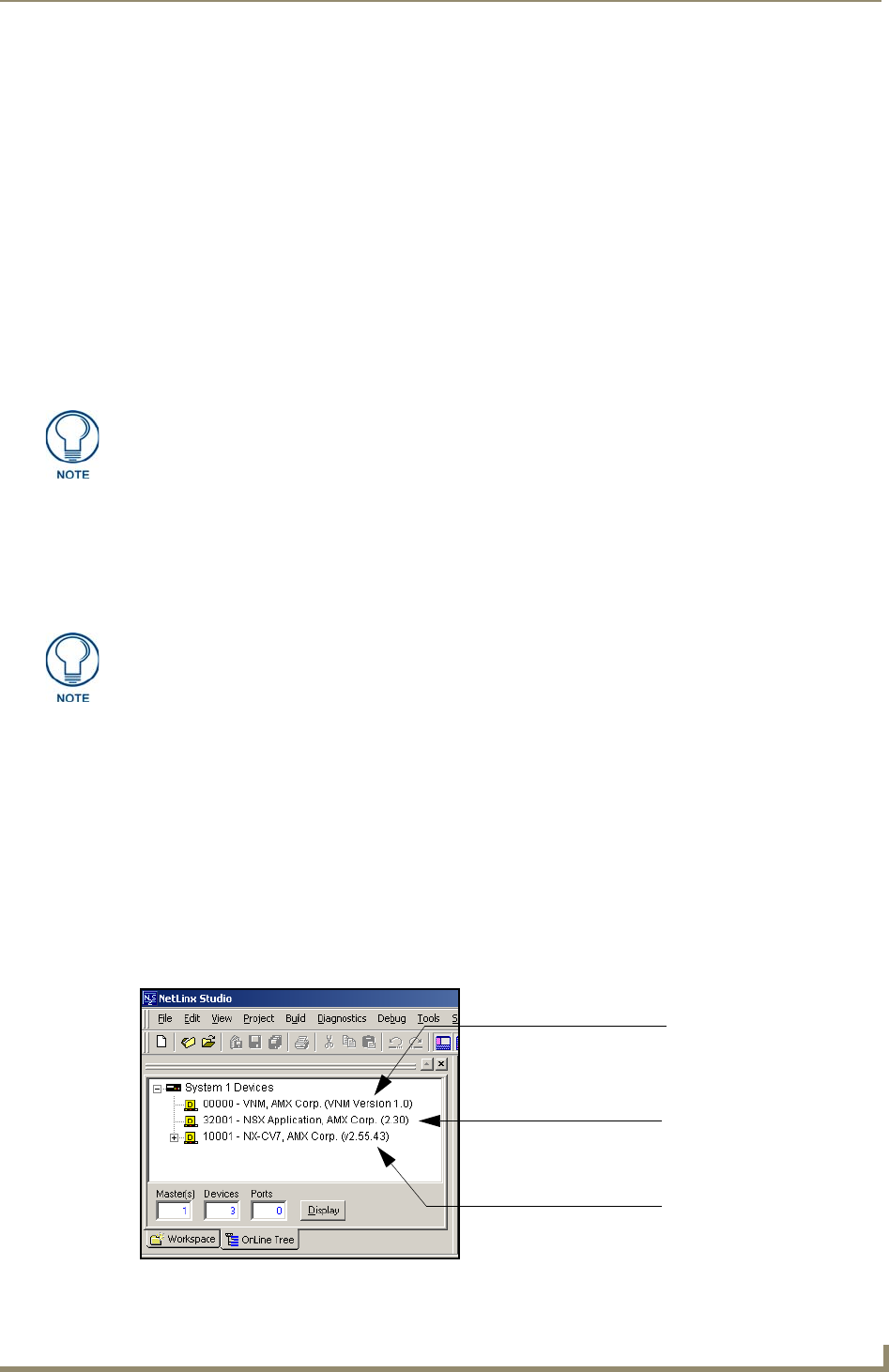
Virtual Master and the panel, click the OnLine Tree tab in the Workspace window (FIG. 78) to
view the devices on the Virtual System. The default System value is one.
4. Right-click on the System entry (FIG. 78) and select Refresh System to re-populate the list.
Verify the panel appears in the OnLine Tree tab of the Workspace window.
The default Modero panel value is 10001.
If the G4 panel does not appear, refer to the Troubleshooting section on page 185 for
more information.
A mini-USB connection is only detected after it is installed onto an active panel.
Connection to a previously powered panel which then reboots, allows the PC to
detect the panel and assign an appropriate USB driver.
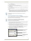
FIG. 78 NetLinx Workspace window (showing the panel connection via a Virtual NetLinx Master)
Showing the Virtual Master
firmware version and
device number
Showing the current Modero
panel firmware version and
device number
Shows NetLinx Studio
version number