


Installation
46
7" Modero Widescreen Touch Panels
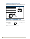
Audio/Video Port: Connections and Wiring
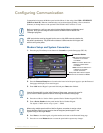
The following table shows the signal and pinout/pairing information used on the RJ-45 Audio and Video
connections.
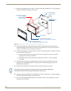
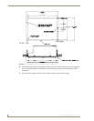
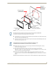
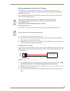
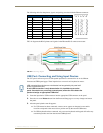
Ethernet/RJ-45 Port: Connections and Wiring
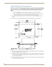
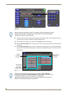
FIG. 43 describes the blink activity for the Ethernet 10/100 Base-T RJ-45 connector and cable. The
Ethernet cable is connected to the rear of Table Top and side of the Wall Mount panels.
Audio/Video RJ-45 Pinout Information
Pin Wire Color Function Polarity
1 Orange/White Right Audio In +
2 Orange Right Audio In -
3 Green/White Video In -
4 Blue Mic Out -
5 White/Blue Mic Out +
6 Green Video In +
7 White/Brown Left Audio In +
8 Brown Left Audio In -
FIG. 43
Ethernet connector (showing communication and connection LEDs)
TIA 568B
1 2 3 4 5 6 7 8
1 2 3 4 5 6 7 8
RJ-45 connector - pin configurations
(female) (male)
ETHERNET
10/100
A L
A - Activity LED (yellow)
lights when receiving or
transmitting Ethernet
data packets
L - Link LED (green) lights when
the Ethernet cables are connected
and terminated correctly.