


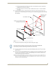

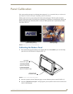
Installation
47
7" Modero Widescreen Touch Panels
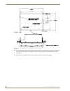
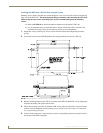
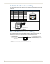
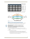
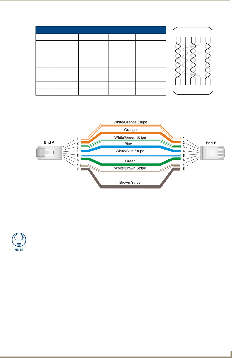
The following table lists the pinouts, signals, and pairing associated with the Ethernet connector.
FIG. 44 diagrams the RJ-45 pinouts and signals for the Ethernet RJ-45 connector and cable.
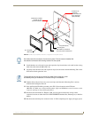
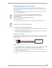
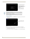
USB Port: Connecting and Using Input Devices
The CV7 panel can have up to two USB-capable input devices connected for use on its different
firmware and TPD4 panel pages. These input devices can consist of a keyboard or mouse.
1. Insert the input device USB connectors into the appropriate USB connector on the panel.
2. Press the on-screen Reboot button from the Protected Setup page to save any changes and restart
the panel.
3. After the panel splash-screen disappears:
If a USB mouse has been connected, a mouse cursor appears on the panel screen and its
location corresponds to the mouse cursor position sent by the external USB mouse.
If a USB keyboard has been connected, only on-screen keyboards and keypads will reflect any
external keystrokes sent from the external USB keyboard.
Ethernet RJ-45 Pinouts and Signals
Pin Signals Connections Pairing Color
1 TX + 1 --------- 1 1 --------- 2 Orange-White
2 TX - 2 --------- 2 Orange
3 RX + 3 --------- 3 3 --------- 6 Green-White
4 no connection 4 --------- 4 Blue
5 no connection 5 --------- 5 4 --------- 5 Blue-White
6 RX - 6 --------- 6 Green
7 no connection 7 --------- 7 7 --------- 8 Brown-White
8 no connection 8 --------- 8 Brown
FIG. 44
RJ-45 wiring diagram
USB-connected input devices are not detected and recognized by the panel until
power is cycled to the unit.
A mini-USB connection is only detected after it is installed onto an active
panel. Connection to a previously powered panel, allows the PC to detect the
panel and assign an appropriate USB driver.
123 456 78
123 456 78