


CV7 Touch Panel Accessories
20
7" Modero Widescreen Touch Panels
4. Rotate the panel back over (while gripping the entire unit and outer housing) and rest the base back
onto a flat surface.
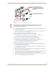
5. Gently tilt the LCD panel backwards to expose the Tilt Bracket/Speaker assembly (FIG. 19).
6. Locate the two screw holes at either sides of the front speaker grill and then use a grounded
Phillips-head screwdriver to remove the two Tilt Bracket Screws (FIG. 17). This procedure both
loosens the rear Tilt Bracket cover plate (with the AMX logo and Hinge brackets) and provides
greater flexibility for the removal of the outer housing. Without this step, the Hinge brackets
(FIG. 17) present an obstacle to the removal of the outer housing and restrict access to the circuit
board.
7. Tilt the LCD panel back up to gain better access to the Tilt Bracket cover plate.
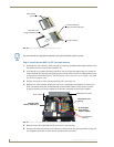
8. In a single motion, carefully pull both the Tilt Bracket cover plate and outer housing up and then out
(away from the LCD panel) to expose the internal circuit board (FIG. 18).
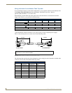
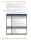
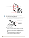
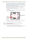
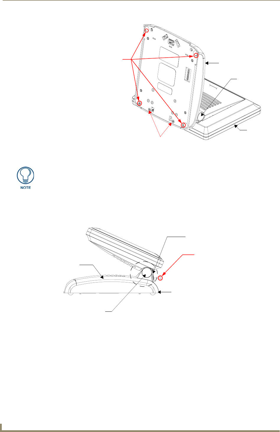
FIG. 16 Location of the attachment screws underneath an NXT-CV7 panel base
Unscrew these four Housing Screws
DO NOT REMOVE these screws
They secure the plastic base front cover.
to remove the Circuit Board Cover
Base
Touch Panel
Hinge Brackets (2)
Note the location of the four plastic adhesive "feet". Once the outer housing is placed
back onto the panel, these "feet" must be placed back onto their original locations so
they can fit into their provided openings on a Battery Base.
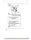
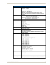
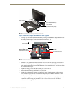
FIG. 17 Location of the Tilt Bracket screws
Base
Outer Housing
Hinge Brackets (2)
Tilt Bracket Screws (2)
These two screws must
first be removed before
being able to remove
the outer housing.
Tilt Bracket/Speaker assembly