


Installation
41
7" Modero Widescreen Touch Panels
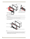
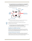
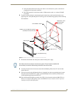
8. Install the three sets of drywall screws and expansion clips into the three oval notch locations along
both sides of the main unit (B in FIG. 39).
9. Carefully insert the main unit (with expansion clips) into the cutout until the Mounting Tabs on the
NXD unit lie flush against the wall.
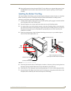
10. Tighten all three drywall clip sets (screws and clips) until the entire Mounting Tab is securely
fastened and flush against the wall.
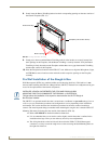
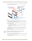
11. Place the Faceplate/Trim Ring assembly (A in FIG. 39) back onto the main NXD unit
(B in FIG. 39). Make sure to align the Microphone, Light, and PIR Motion sensor locations to their
respective openings on the front faceplate/bezel.
12. Reconnect the terminal RJ-45, Ethernet, USB, and any optional audio/video wiring to their
respective locations on either the NXA-AVB/ETHERNET Breakout Box, Ethernet port, or NetLinx
Master.
13. Reconnect the terminal power connector on the 12 VDC-compliant power supply and apply power.
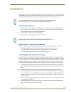
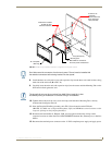
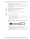
FIG. 39 Wall Mount panel (NXD) installation configuration for drywall surfaces
B - Main NXD unit consists of
Install the 3 included
drywall clip sets
into these locations
the touch panel and back box
3 notches are
required to
accommodate the
three expansion
clips (included)
A - Faceplate
/Trim Ring
Mounting Tab
Drywall Clip (3)
Don’t disconnect the connectors from the touch panel. The unit must be installed with
the attached connectors before being inserted into the drywall.
The drywall clip set must be re-ordered from AMX if the drywall clip is bent
accidentally during an installation or removed during a re-installation.