


Troubleshooting 9-3
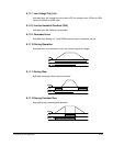
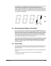
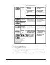
If the application is using digital outputs to reflect the internal status of the drive, these
can be monitored using parameter d8. The below describes the details of
understanding the status of each of the digital outputs (labeled MO for the open
collector output and 3A/3B/3C for the relay output on the control board terminal strip).
In this example, the multi-function output MO is “ON” and the multi-function relay is
“OFF” (note that the indication for the multi-function relay is an indication of whether or
not the relay coil is energized).
9.4 Reviewing Fault Status of the Drive
As noted in Chapter 6, the Display Group has an entry that designates if there is an
active fault and will display the fault code associated with that fault. The fault codes
are described later in this chapter. While displaying the fault code within the Display
Group, you can press the enter key to display the frequency the drive was running at
when the fault occurred. By pressing the up arrow one time, you can display the
current the drive detected when the fault occurred. By pressing the up arrow again,
you will display the drive status when the fault occurred.
Function Group 2 (H parameters) also contains the current fault along with a history of
the previous 4 faults. These faults are located at parameters H1, H2, H3, H4, and H5.
As with the fault memory in the Display Group, you can subsequently display the
frequency, current, and status for each of these faults using the same procedure
outlined in Chapter 6.
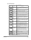
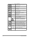
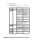
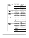
9.5 Fault Codes
Fault codes indicate conditions within the drive that require immediate attention. The
drive responds to a fault by initiating a coast-to-stop sequence and turning off the
power to the motor.
The integral keypad provides visual notification of a fault condition by displaying the
following:
• Fault code on the display. (See table 9.1 for the fault code descriptions.)
• Flashing STP/FLT LED
(ON
)
(OFF
)
MO3A/3B