


B-8 VS1MD User Manual
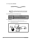
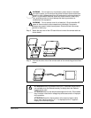
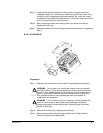
Step 4. Remove two screws and cover from front of conduit kit. Retain screws.
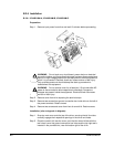
Installation:
Step 1. Slide conduit kit into slots in bottom of drive from which wire gland plate was
removed.
Step 2. Install the two screws removed from the wire gland plate during preparation
Step 3 such that they are inserted through the two holes in the conduit kit
prior to engaging the tapped holes in the drive.
Step 3. After connecting conduits and making control and power connections,
replace the drive cover.
Step 4. Replace the conduit kit cover utilizing the two screws removed in preparation
Step 4.
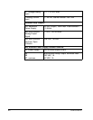
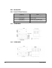
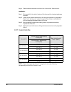
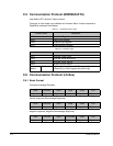
B.2.7 Conduit Hole Size
NOTE: Choose the proper size of the UL recognized Locknut and Bushing
corresponding to size of the Conduit in use.
Conduit Kit
Conduit hole for control wiring
inches (mm)
Size of the Conduit
Inches (Metric)
Conduit hole for power wiring
inches (mm)
VS1MD-NM1A
0.87 (22.2) 1/2 (16)
0.87 (22.2) 1/2 (16)
VS1MD-NM1B
0.87 (22.2) 1/2 (16)
0.87 (22.2) 1/2 (16)
VS1MD-NM1C
0.87 (22.2) 1/2 (16)
0.87 (22.2) 1/2 (16)
VS1MD-NM1D
0.87 (22.2) 1/2 (16)
1.38 (35.0) 1 (27)