


Options & Kits B-7
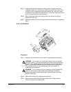
Step 3. Install the two screws removed from the ground connection bar during
preparation Step 3 such that they are inserted through the two holes in the
conduit kit prior to engaging the ground connection bar. Install the screw
provded with the conduit kit through the hole in the bottom right corner of the
drive into the top right tab of the conduit kit.
Step 4. After connecting conduits and making control and power connections,
replace the drive cover.
Step 5. Replace the conduit kit cover utilizing the two screws removed in preparation
Step 4.
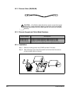
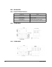
B.2.6.2 VS1MD-NM1D
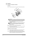
Preparation:
Step 1. Remove input power from drive and wait 10 minutes before proceeding.
Step 2. Remove cover from drive, exposing terminal strips.
Step 3. Remove two screws holding wire gland plate to drive. Retain screws.
Remove and discard wire gland plate.
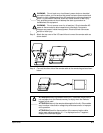
!
!
WARNING: Do not touch any circuit board, power device or electrical
connection before you first ensure that power has been disconnected and
there is no high voltage present from this equipment or other equipment to
which it is connected. Electrical shock can cause serious or fatal injury.
Only qualified personnel should attempt the start-up procedure or
troubleshoot this equipment.
!
!
WARNING: Do not remove cover for at least ten (10) minutes after AC
power is disconnected to allow capacitors to discharge. Dangerous
voltages are present inside the equipment. Electrical shock can cause
serious or fatal injury.