


7-14 VS1MD AC Drive User Manual
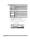
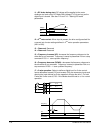
11 = DC brake during start: DC voltage will be applied to the motor
windings at a level set by DC Brake Start Voltage (F12) for as long as the
digital input is closed. See also F12 and F13 – Starting DC brake
parameters.
12 = 2
nd
motor select: When input is present, the drive configures itself for
a second set of motor settings defined in 2
nd
motor operation parameters
(H81 to H90).
13 = Reserved: Reserved
14 = Reserved: Reserved
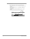
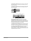
15 = Frequency increase (UP): Increases the frequency reference to the
drive after a run command. Frequency is saved to parameter F64 on a stop
command if F63 = 1 ‘save up/down frequency’.
16 = Frequency decrease (DOWN): decreases the frequency reference to
the drive after a run command. Frequency is saved to parameter F64 on a
stop command if F63 = 1 ‘save up/down frequency’.
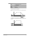
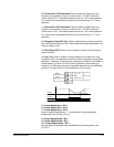
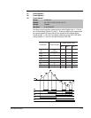
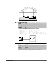
17 = 3-wire operation: Select to define a digital input for 3-wire control.
Inputs defined as forward (FX) and reverse (RX) are momentary inputs and
opening the input defined as 3-wire operation will stop the drive. For both
2-wire and 3-wire control, P38 – Drive Mode should be set to a 1 for normal
operation.
Voltage
Run
command
F12
P3
P1
P2
P8
CM
FX : t1 = 0
RX : t2 = 1
3-Wire : t8 = 17
FX
RX
Frequency
P8 (3-Wire)
t