


Parameter Descriptions 7-15
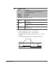
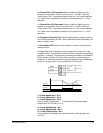
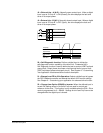
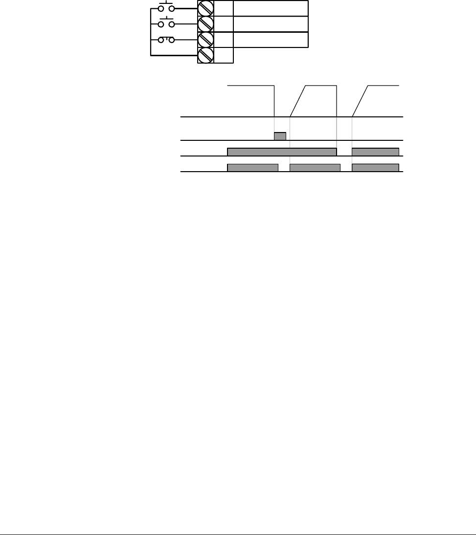
18 = External trip – A (N.O.): Normally open contact input. When a digital
input is set to “Ext trip-A” is ON (Closed), the drive displays the fault and
turns off its output power.
19 = External trip – B (N.C.): Normally closed contact input. When a digital
input is set to “Ext trip-B” is OFF (Open), the drive displays the fault and
turns off its output power.
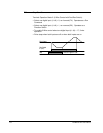
20 = Self-Diagnostic function: Defines a digital input to initiate the
self-diagnostic function capability of the drive unit. Parameter H60 =
Self-Diagnostic function is used to define the test to conduct; IGBT fault and
ground fault, Output phase short/open circuit/ground fault or ground fault
(IGBT fault/output phase short/open circuit). See Chapter 8 – Customizing
Your Application for advanced drive function description.
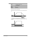
21 = Change from PID to V/Hz Operation: Selects a digital input to bypass
the PID Feedback controller and selects the default V/Hz control settings.
See Chapter 8 – Customizing your application for advanced drive function.
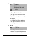
22 = Change from Option (RS485) to Inverter: When the defined input is
turned ON, setting values in drv2 and Frq2 are used for control and
reference to the drive. This function is only available when the P38 = Drive
mode is programmed for 3 = RS485. Settings for drv2 and Frq2 can not be
changed while the digital input is closed.
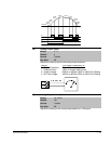
P1
P7
P8
FX : t1 = 0
N.O. : t2 = 18
CM
N.C. : t8 = 19
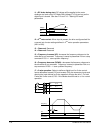
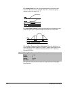
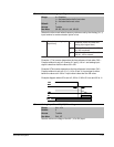
P4(A contact)
Frequency
Run
command
P5(B contact)