


Chapter 5 Trial Run and Tuning Procedure|ASDA-B Series
Revision February 2008, Doc. Name: 2006PDD23000009 5-11
5.5 Tuning Procedure
ASD-PU-01A
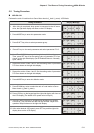
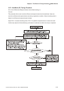
Estimate the ratio of Load Inertia to Servo Motor Inertia (J_load /J_motor): JOG Mode
Tuning Procedure Display Message
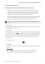
1. After wiring is completed, when power in connected to the AC servo
drive, the right side display will show on the LCD display.
W M
FARAM
C
CL
L
IT R E R I
2. Press MODE key to enter into parameter mode.
1
EVP
:
0
-
0
0
0R
.08
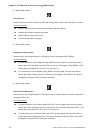
3. Press SHIFT key twice to select parameter group.
PKP
:
0
-
02P
50 / sadr
4. Press UP key to view each parameter and select parameter P2-13.
IDP
:
1
-
324
22
5. Use UP and DOWN key to cycle through the available settings.
Then, press SET key to set the setting value of parameter P2-13 as
shown on the right side display (Set DI Enabled Status to “Normally
open” status).
IDP
:
1
-
324
221
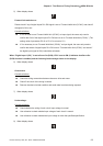
6. Repeat the action of item 4 and 5. Set the setting value of parameter
P2-14 as shown on the right side display.
IDP
:
1
-
425
231
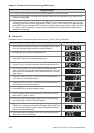
7. Repeat the action of item 4 and 5. Set the setting value of parameter
P2-15 as shown on the right side display.
IDP
:
1
-
526
211
8. Press MODE key to enter into Monitor mode.
bFS
:
0T
S
0
0
L
P
US
E
l
p
u
s
e
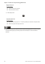
9. Press DOWN key twice to select the ratio of Load Inertia to Servo
Motor Inertia (J_load /J_motor).
S
:
TS1
0
JL4
m
iet.3
10. Press JOG key on the keypad and the right side display will show on
the LCD display (The default JOG speed value is 20rpm.)
OJP
:
0
-
54G
20 pmr
11. Press UP and DOWN key to increase and decrease JOG speed.
Press SHIFT key one time can add one digit number. Adjust JOG
speed as 200rpm shown on the right side display.
OJP
:
0
-
54G
00 pmr2
12. After select desired JOG speed, press SET key and the right side
display show on the LCD display.
OJP
:
0
-
54G
pmr
OJG