


Chapter 6 Control Modes of Operation|ASDA-B Series
Revision February 2008, Doc. Name: 2006PDD23000009 6-7
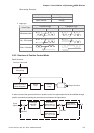
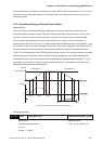
The equation is shown as follows:
fp<
fv
4
, fv : Speed Loop Responsiveness (Hz), fp : Position Loop Responsiveness (Hz)
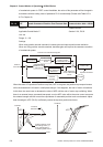
KPP = 2 × π × fp.
For example, the desired position loop responsiveness is equal to 20 Hz.
Then, KPP = 2 × π × 20= 125 rad/s.
Relevant parameters:
P2 - 00
KPP Proportional Position Loop Gain Communication Addr.: 0200H
Default: 50 Related Section:
Applicable Control Mode: P Section 6.2.6, P2-27
Unit: rad/s
Range: 0 ~ 1023
Settings:
This parameter is used to set the position loop gain. It can increase stiffness, expedite position
loop response and reduce position error. However, if the setting value is over high, it may
generate vibration or noise. In AutoMode, the value of this parameter will be changed in
accordance with the setting value of parameter P2-31 automatically (Please refer Table 6.D &
6.E in Chapter 6).
P2 - 01
PPR Position Loop Gain Switching Rate Communication Addr.: 0201H
Default: 100 Related Section:
Applicable Control Mode: P Section 6.2.6, P2-27, P2-29
Unit: %
Range: 10 ~ 500
Settings:
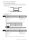
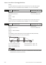
This parameter is used to set the position gain switching rate when the gain switching condition
is satisfied. Please refer to P2-27 for gain switching control selection settings and refer to P2-29
for gain switching condition settings.
P2 - 02
PFG Position Feed Forward Gain Communication Addr.: 0202H
Default: 0 Related Section:
Applicable Control Mode: P Section 6.2.6, P2-03
Unit: %
Range: 0 ~ 100
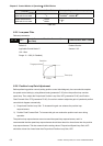
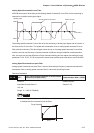
This parameter is used to set the feed forward gain when executing position control command.
When using position smooth command, increase gain can improve position track deviation.
When not using position smooth command, decrease gain can improve the resonance condition