


Chapter 3 Connections and Wiring|ASDA-B Series
Revision February 2008, Doc. Name: 2006PDD23000009 3-25
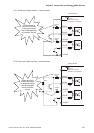
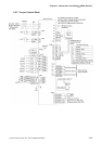
3.5 Serial Communication Connector CN3
3.5.1 CN3 Terminal Layout and Identification
The servo drive can be connected to a PC or controller via a serial communication connector. The users
can operate the servo drive through PC software supplied by Delta (contact to the dealer/distributor).
The communication connector/port of Delta servo drive can provide two common serial communication
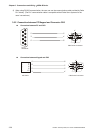
interfaces: RS-232, and RS-485 connection. RS-232 is mostly be used but is somewhat limited. The
maximum cable length for an RS-232 connection is 15 meters (50 feet). Using RS-485 interface can
allow longer distance for transmission and support multiple drives to be connected simultaneously.
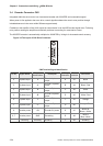
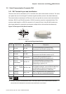
Figure 3.9 The layout of CN3 Drive Connector:
1
2
3
4
5
6
7
8
CN3 Drive Connector
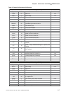
CN3 Terminal Signal Identification
Pin No Signal Name
Terminal
Identification
Description
1 RS-485- RS-485-
For data transmission of the servo drive.
Connected to the RS-485- interface of PC.
2 Signal power +5VD
3 RS-485+ RS-485+
For data transmission of the servo drive.
Connected to the RS-485+ interface of PC.
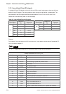
4
RS-232 data
receiving
RS-232-RX
For data receiving of the servo drive.
Connected to the RS-232 interface of PC.
5
RS-232 data
transmission
RS-232-TX
For data transmission of the servo drive.
Connected to the RS-232 interface of PC.
Please refer to section 3.5.2.
6
RS-232 / RS-485
data format
selection
SEL232 / 485
RS-232 & RS-485 data format selection
For RS-485 connection, connect SEL232/485(Pin6)
to GND(Pin8). For RS-232 connection, do not
connect SEL232/485(Pin6) to GND(Pin8).
7
Re-flash
selection
Boot_Load
Boot_Load terminal for DSP Reflash burn-in
selection (Do not connect this terminal).
8 Grounding GND
NOTE
1) In order to avoid the communication error, if the users use their own communication connector,
ensure the circuit between the connector case and all pins is not closed.