


Chapter 7 Servo Parameters|ASDA-B Series
7-74 Revision February 2008, Doc. Name: 2006PDD23000009
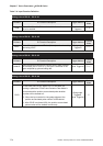
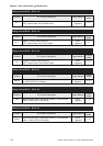
Table 7.A Input Function Definition
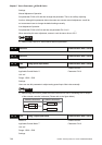
Setting value of P2-10 ~ P2-15: 01
DI Name DI Function Description Trigger Method
Control
Mode
SON
Servo On. When this DI is activated, it indicates the servo
drive is enabled.
Level
Triggered
P, S, T
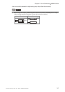
Setting value of P2-10 ~ P2-15: 02
DI Name DI Function Description Trigger Method
Control
Mode
ARST
Alarm Reset. A number of Faults (Alarms) can be cleared by
activating ARST.
Rising-edge
Triggered
P, S, T
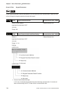
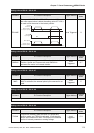
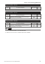
Setting value of P2-10 ~ P2-15: 03
DI Name DI Function Description Trigger Method
Control
Mode
GAINUP
Gain switching in speed and position mode. When GAINUP
is activated (P2-27 is set to 1), the gain is switched to the
gain multiplied by gain switching rate.
Level Triggered P, S, T
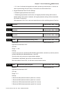
Setting value of P2-10 ~ P2-15: 04
DI Name DI Function Description Trigger Method
Control
Mode
CCLR
Pulse clear (see P2-48). When CCLR is activated, the
setting is parameter P2-48 Pulse Deviation Clear Mode is
executed and the position accumulated pulse deviation
number will be cleared to 0.
0: When the input terminal is rising-edge triggered, the
position accumulated pulse number will be cleared.
1: After CCLR is activated (ON), the position accumulated
pulse number will be cleared continuously.
Rising-edge
Triggered,
Level Triggered
P