


Chapter 6 Control Modes of Operation|ASDA-B Series
Revision February 2008, Doc. Name: 2006PDD23000009 6-15
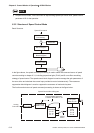
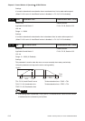
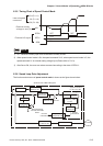
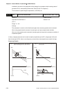
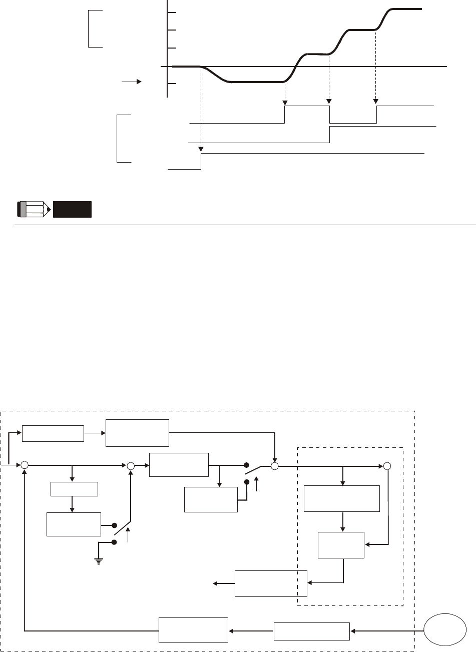
6.3.5 Timing Chart of Speed Control Mode
S4 (P1-11)
S3 (P1-10)
S2 (P1-09)
S1
SPD0
SPD1
SON
OFF
ON
OFF
ON
ON
OFF
ON
Internal speed
command
External analog
voltage or zero (0)
External I/O signal
NOTE
1) OFF indicates normally open and ON indicates normally closed.
2) When speed control mode is Sz, the speed command S1=0; when speed control mode is S, the
speed command S1 is external analog voltage input (Please refer to P1-01).
3) After Servo ON, the users can select command according to the state of SPD0~1.
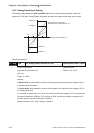
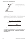
6.3.6 Speed Loop Gain Adjustment
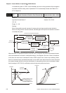
The function and structure of speed control mode is shown as the figure shown below:
Feed Forward
Gain P2-07
Proportional
Gain P2-04
+
-
Switching
Rate P2-05
J_load /J_motor
P1-37
Gain Switching
Control Selection
P2-27
+
+
Differentiator
+
+
P2-27
+
+
System inertia J
(1+P1-37)*JM
Torque constant
reciprocal 1/KT
Motor
Inertia JM
Torque
Command
Current
Command
Low-pass
Filter P2-49
Speed Control Block Diagram
Encoder
Speed Estimator
Proportional
Gain P2-04
Integrator