


Chapter 8 MODBUS Communications|ASDA-B Series
Revision February 2008, Doc. Name: 2006PDD23000009 8-13
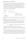
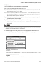
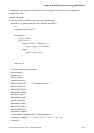
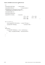
CRC (RTU Mode):
CRC (Cyclical Redundancy Check) is calculated by the following steps:
Step 1: Load a 16-bit register (called CRC register) with FFFFH.
Step 2: Exclusive OR the first 8-bit byte of the command message with the low order byte of the 16-bit CRC
register, putting the result in the CRC register.
Step 3: Extract and examine the LSB. If the LSB of CRC register is 0, shift the CRC register one bit to the
right. If the LSB of CRC register is 1, shift the CRC register one bit to the right, then Exclusive OR
the CRC register with the polynomial value A001H.
Step 4: Repeat step 3 until eight shifts have been performed. When this is done, a complete 8-bit byte will
have been processed, then perform step 5.
Step 5: Repeat step 2 to step 4 for the next 8-bit byte of the command message.
Continue doing this until all bytes have been processed. The final contents of the CRC register are
the CRC value.
NOTE
1) When transmitting the CRC value in the message, the upper and lower bytes of the CRC value must be
swapped, i.e. the lower order byte will be transmitted first.
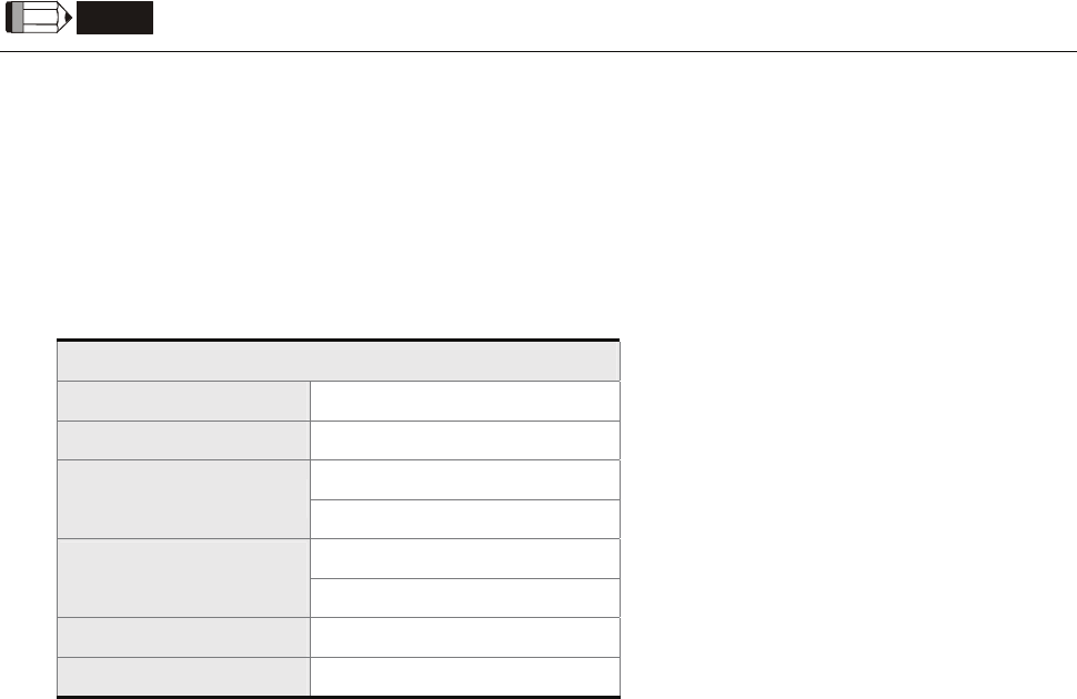
2) For example, reading 2 words from address 0101H of the AC servo drive with address 01H. The final
content of the CRC register from ADR to last data character is 3794H, then the command message is
shown as follows. What should be noticed is that 94H have to be transmitted before 37H.
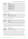
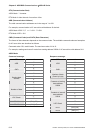
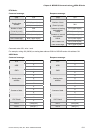
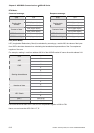
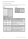
Command Message
ADR 01H
CMD 03H
01H (Upper byte)
Starting data address
01H (Lower bytes)
00H (Upper bytes)
Number of data
(Count by word)
02H (Lower bytes)
CRC Check Low 94H (Lower bytes)
CRC Check High 37H (Upper bytes)
End1, End0 (Communication End)
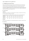
ASCII Mode:
In ASCII mode, (0DH) stands for character ’\r’ (carriage return) and (0AH) stands for character ’\n’ (new
line), they indicate communication end.
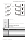
RTU Mode:
In RTU mode, a silent interval of more than 10ms indicates communication end.