


Chapter 3 Connections and Wiring|ASDA-B Series
Revision February 2008, Doc. Name: 2006PDD23000009 3-17
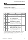
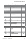
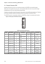
Table 3.F Default DI Signals and DO Signals
The factory default settings of DI signals
Signal DI Code Function Default Settings
SON 01 Servo On DI1
ARST 02 Alarm Reset DI2
GAINUP 03 Gain switching in speed and position mode
CCLR 04 Pulse clear DI3
ZCLAMP 05 Zero speed CLAMP
CMDINV 06 Command input reverse control
INHP 07 Pulse inhibit input
TRQLM 09 Torque limit enabled
SPDLM 10 Speed limit enabled
GNUM0 11 Electronic gear ratio (Numerator) selection 0
SPD0 14 Speed command selection 0
SPD1 15 Speed command selection 1
TCM0 16 Torque command selection 0
TCM1 17 Torque command selection 1
S-P 18
Position / Speed mode switching (OFF: Speed, ON:
Position)
S-T 19
Speed / Torque mode switching (OFF: Speed, ON:
Torque)
T-P 20
Torque / Position mode switching (OFF: Torque,
ON: Position)
EMGS 21 Emergency stop (contact b) DI6
CWL 22 Reverse inhibit limit (contact b) DI4
CCWL 23 Forward inhibit limit (contact b) DI5
TLLM 25 Torque limit - Reverse operation
TRLM 26 Torque limit - Forward operation
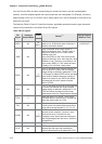
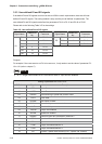
The factory default settings of DO signals
Signal DO Code Function Default Settings
SRDY 01 Servo ready DO1
SON 02 Servo On
ZSPD 03 At Zero speed DO2
TSPD 04 At Speed reached
TPOS 05 At Positioning completed
TQL 06 At Torques limit
ALRM 07 Servo alarm (Servo fault) activated DO3
BRKR 08 Electromagnetic brake control
OLW 09 Output overload warning
WARN 10 Servo warning activated