


Chapter 6 Control Modes of Operation|ASDA-B Series
6-18 Revision February 2008, Doc. Name: 2006PDD23000009
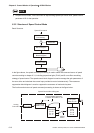
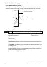
• Tuning Mode Settings:
0: Manual mode
1: AutoMode (Continuous adjustment)
The ratio of Load Inertia to servo motor inertia can be continuously adjusted.
The level of stiffness and responsiveness are adjusted by parameter P2-31.
2: AutoMode (The ratio of Load Inertia to servo motor inertia is fixed)
The ratio of Load Inertia to servo motor inertia is set by parameter P1-37.
The level of stiffness and responsiveness are adjusted by parameter P2-31.
• Control Loop Structure Settings:
0: PDFF Control. PDFF : Pseudo-Derivative Feedback and Feedforward
1: PI Control. PI : Proportional - Integral control
Explanation of Auto-tuning:
1. When switching mode #1 to #2 or #0, the system will save the measured load inertia value
automatically and memorized in P1-37 and related gain parameters.
2. In AutoMode #1, the system will save the measured load inertia value every 30 minutes
automatically and memorized in P1-37.
3. In AutoMode #2, if the setting value of P2-31 changes, the related gain parameters will also
change. However, the setting value of P1-37 will retain its value.
4. When switching mode #2 to #0, it indicates the setting of P1-37 and all settings of related
gain parameters will be returned to original setting value in #0 manual mode.
5. No matter in Manual mode #0 or in AutoMode #2, the users should enter the appropriate
load inertia value in P1-37.
6. If the users use the servo dynamic auto-tuning function of ASDA-B software (Tools Æ Servo
Tuning Æ Dynamic Auto tuning), it will save the measured load inertia value and memorized
in P1-37 and related gain parameters.
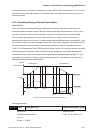
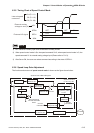
Manual Mode
When·Tuning Mode Settings of P2-32 is set to 0, the users can define the proportional speed loop gain
(P2-04), speed integral gain (P2-06) feed forward gain (P2-07) and ratio of load inertia to servo motor
Inertia (1-37). Please refer to the following description:
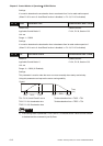
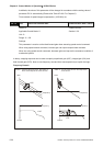
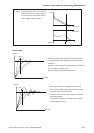
Proportional gain: Adjust this gain can increase the position loop responsiveness.
Integral gain: Adjust this gain can enhance the low-frequency stiffness of speed loop and
eliminate the steady error. Also, reduce the value of phase margin. Over high integral gain will
result in the unstable servo system.
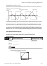
Feed forward gain: Adjust this gain can decrease the phase delay error
NOTE
1) Before adjusting the gain manually, ensure to set P1-37 in advance. If the setting value of P1-37 is
quite different than the actual load inertia ratio, the responsiveness that represented by P2-04 has
no meaning.