


Chapter 3 Connections and Wiring|ASDA-B Series
3-20 Revision February 2008, Doc. Name: 2006PDD23000009
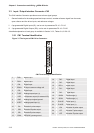
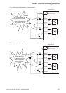
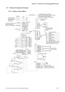
3.3.4 Wiring Diagrams of I/O Signals (CN1)
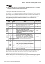
The valid voltage range of analog input command in speed and torque mode is -10V ~+10V.
The command value can be set via relevant parameters.
C1: Speed / Torque analog signal input
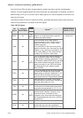
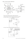
There are two kinds of pulse inputs, Line driver input and Open-collector input. Max. input pulse
frequency of Line driver input is 500kpps and max. input pulse frequency of Open-collector input is
200kpps.
NOTE
1) In order to protect the internal circuit, when using open collector input, please
ensure to connect one 1 ~ 2 KΩ current limit resistor before Pin 19(/SIGN) and
Pin 21(/PULSE) respectively (Please refer to the wiring diagram on next page).
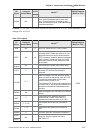
2) For the specifications of connected current limit resistor, please refer to the
table below:
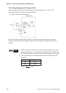
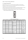
Vdc Specifications
24V 1KΩ
12V 500Ω
Equation: mA
R
20
100
2Vdc
≅
+
−