


Chapter 7 Servo Parameters|ASDA-B Series
7-36 Revision February 2008, Doc. Name: 2006PDD23000009
P1 - 44▲
GR1 Electronic Gear Ratio (1st Numerator) (N1) Communication Addr.: 012CH
Default: 1 Related Section:
Applicable Control Mode: P Section 6.2.4, P1-15, P1-45
Unit: pulse DI GNUM0(11) in Table 7.A
Range: 1 ~ 32767
Settings:
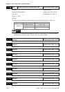
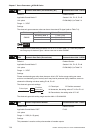
The electronic gear numerator value can be set via external DI signal (refer to Table 7.A).
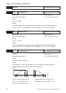
DI Name DI Status Selected Electronic Gear
Not select (Note 1) P1-44, P1-45
0 P1-44, P1-45
GNUM0
1 P1-44, P1-45
NOTE
1) DI signal can be selected by parameter P2-10 to P2-15 and Table 7.A. If uses only need to
use one group of electronic gear, it allows users not to select GNUM0.
P1 - 45▲
GR2 Electronic Gear Ratio (Denominator) Communication Addr.: 012DH
Default: 1 Related Section:
Applicable Control Mode: P Section 6.2.4, P1-15, P1-44
Unit: pulse DI GNUM0(11) in Table 7.A
Range: 1 ~ 32767
Settings:
Please set electronic gear ratio when the servo drive is Off. As the wrong setting can cause
motor to run chaotically (out of control) and it may lead to personnel injury, therefore, ensure to
observe the following rule when setting P1-44, P1-45.
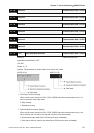
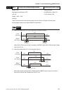
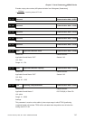
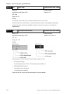
The electronic gear ratio settings:
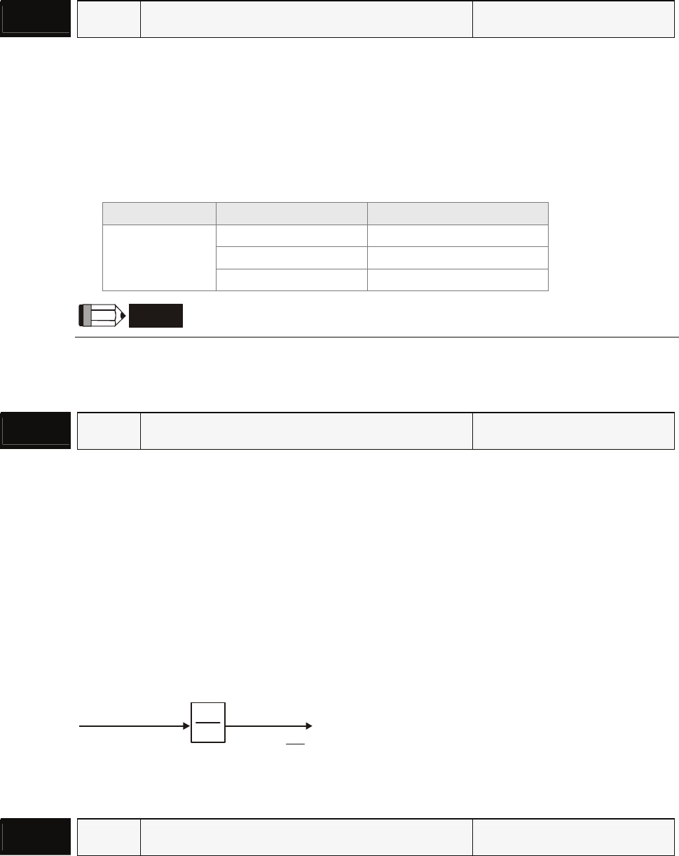
f1
f2 = f1 x
N
M
N
M
Pulse input
Position
command
The electronic gear ratio setting range must be within: 1/50<N/M<200.
P1 - 46▲
GR3 Encoder Output Pulse Number Communication Addr.: 012EH
Default: 2500 Related Section:
Applicable Control Mode: P/S/T P1-03
Unit: pulse
Range: 1 ~ 2500 (0 = By pass)
Settings:
This parameter is used to set the pulse number of encoder outputs.
f1: Pulse input f2: Position command
N: Numerator, the setting value of P1-15 or P1-44
M: Denominator, the setting value of P1-45