


Chapter 12 Application Examples|ASDA-B Series
12-14 Revision February 2008, Doc. Name: 2006PDD23000009
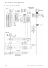
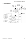
ASDA-B series Servo Drive
Parameter Settings:
P1-00 =0 (Position mode)
P2-10 =101 (SON Servo ON, the default is DI1)
P2-12 =104 (CCLR)
P2-32 =1 (PDFF, the ratio of load inertia to servo motor inertia can be continuously adjusted.)
Communication Settings:
Use RS-485 communication
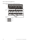
Operation
Ensure all wiring is connected correctly.
Restart the servo drive (Apply the power to servo drive again).
At this time, the SON LED (Servo On Indicator) will be lit to indicate that the servo drive is enabled, and
normal display will show on the LCD display. If ALRM LED (Alarm Output Indicator) is lit or any fault
message show on the LCD display, please refer to Chapter 10 “Troubleshooting” to remove the fault
code and fault message.
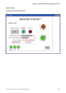
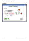
If there is no fault, set the speed of homing operation and the setting value of speed 2 on the first TP04
screen.
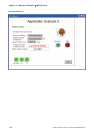
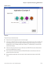
Press “Servo On” key on the second TP04 screen and CMD LED will be red to indicate that the servo
drive is enabled (Servo On status).
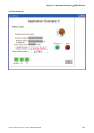
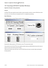
Then, the users can use homing function on the third TP04 screen to control the servo drive.
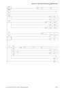
Finally, the users can observe the servo operation on the forth TP04 screen.