


Chapter 7 Servo Parameters|ASDA-B Series
7-76 Revision February 2008, Doc. Name: 2006PDD23000009
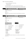
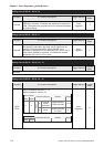
Setting value of P2-10 ~ P2-15: 10
DI Name DI Function Description Trigger Method
Control
Mode
SPDLM
Speed limit enabled. When the drive is in torque mode and
SPDLM is activated, it indicates the speed limit command is
valid. The speed limit command source is internal parameter
or analog voltage.
Level
Triggered
T
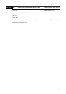
Setting value of P2-10 ~ P2-15: 11
DI Name DI Function Description Trigger Method
Control
Mode
GNUM0
Electronic gear ratio (Numerator) selection. When users use
two groups of electronic gear ratio, this DI signal can be
used to switch the Numerator. When GNUM0 is not
activated, it indicates the first Numerator (N1, see P1-44) is
used. When GNUM0 is activated, it indicates the second
Numerator (N2, see P1-15) is used.
Level
Triggered
P
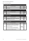
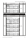
Setting value of P2-10 ~ P2-15: 12 ~ 13
DI Name DI Function Description Trigger Method
Control
Mode
Reserved
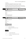
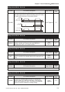
Setting value of P2-10 ~ P2-15: 14 ~ 15
DI Name DI Function Description Trigger Method
Control
Mode
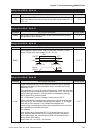
SPD0
SPD1
Speed command selection (1 ~ 4)
Speed command number: S1
CN1 DI signal
SPD1 SPD0
Command Source Content Range
S
External
analog
command
Voltage between
V-REF and GND
+/-10 V
0 0
Mode
Sz None
Speed command
is 0 (zero)
0
Speed command number: S2
CN1 DI signal
SPD1 SPD0
Command Source Content Range
Level
Triggered
S