


Chapter 3 Connections and Wiring|ASDA-B Series
Revision February 2008, Doc. Name: 2006PDD23000009 3-13
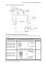
NOTE
1) GND (Pin 8) and COM- (Pin 13) of CN1 connector are independent respectively and do not have
connection with the ground terminal outside the servo drive.
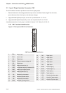
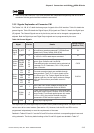
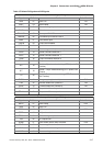
3.3.2 Signals Explanation of Connector CN1
The Tables 3.A, 3.B, & 3.C detail the three groups of signals of the CN1 interface. Table 3.A details the
general signals. Table 3.B details the Digital Output (DO) signals and Table 3.C details the Digital Input
(DI) signals. The General Signals are set by the factory and can not be changed, reprogrammed or
adjusted. Both the Digital Input and Digital Output signals can be programmed by the users.
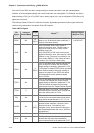
Table 3.A General Signals
Signal Pin No Details
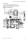
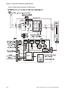
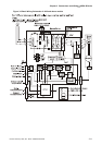
Wiring Diagram
(Refer to 3.3.3)
V_REF 9
Motor speed command: -10V to +10V, corresponds to
the maximum speed programmed P1-55 Maximum
Speed Limit (Factory default 3000 RPM).
C1
Analog
Signal
Input
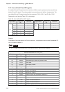
T_REF 6
Motor torque command: -10V to +10V, corresponds
to -100% to +100% rated torque command.
C1
Position
Pulse
Input
PULSE
/PULSE
SIGN
/SIGN
22
21
20
19
The drive can accept two different types of pulse
inputs: Open Collector and Line Driver.
Three different pulse commands can be selected via
parameter P1-00. Quadrature, CW + CCW pulse &
Pulse / Direction.
C2/C3
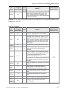
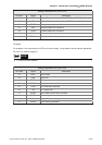
OA
/OA
10
23
OB
/OB
12
11
Position
Pulse
Output
OZ
/OZ
24
25
The motor encoder signals are available through
these terminals. The A, B, Z output signals can be
Line Driver type. The Z output signal can be Open
Collector type also, but the output maximum voltage
is 5V and the maximum permissible current is
200mA.
C10/C11
VDD 7
VDD is the +24V source voltage provided by the
drive. Maximum permissible current is 500mA.
Power
COM+
COM-
4
13
COM+ is the common voltage rail of the Digital Input
and Digital Output signals. Connect VDD to COM+ for
source mode. For external applied power sink mode
(+12V to +24V), the positive terminal should be
connected to COM+ and the negative to COM-.
-
Ground
GND 8 Analog input signal ground.
-
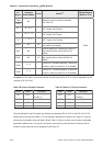
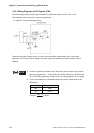
The Digital Input (DI) and Digital Output (DO) have factory default settings which correspond to the
various servo drive control modes. (See section 1.5). However, both the DI's and DO's can be
programmed independently to meet the requirements of the users.
Detailed in Tables 3.B and 3.C are the DO and DI functions with their corresponding signal name and
wiring schematic. The factory default settings of the DI and DO signals are detailed in Table 3.F.