


Chapter 4 Display and Operation|ASDA-B Series
Revision February 2008, Doc. Name: 2006PDD23000009 4-15
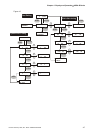
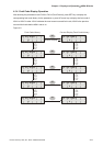
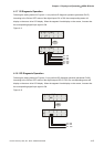
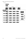
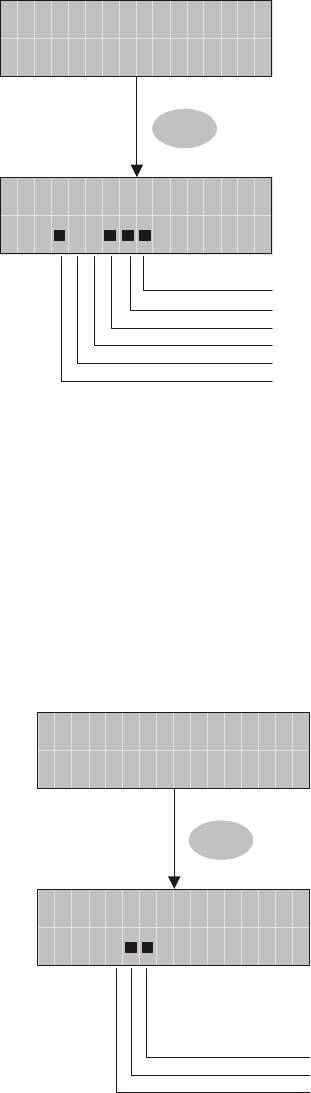
4.1.7 DI Diagnosis Operation
Following the setting method in Figure 4.11 can perform DI diagnosis operation (parameter P4-07).
According to the ON and OFF status of the digital inputs DI1 to DI6, the corresponding status will
display on the servo drive LCD display. When the segment lit and display on the screen, it means that
the corresponding digital input signal is ON.
Figure 4.11
T
I
P
:
04
-
7
S
7
SET
DI
T
5
TIP
:
04
-
7ST
DI6: ON
DI5: ON
DI4: ON
DI3: OFF
DI2: OFF
DI1: ON
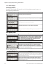
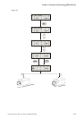
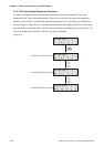
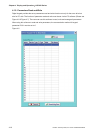
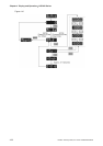
4.1.8 DO Diagnosis Operation
Following the setting method in Figure 4.12 can perform DO diagnosis operation (parameter P4-09).
According to the ON and OFF status of the digital outputs DO1 to DO3, the corresponding status will
display on the servo drive LCD display. When the segment lit and display on the screen, it means that
the corresponding digital input signal is ON.
Figure 4.12
O
M
P
:
04
-
9
H
DO
T
6
P
:
04
-
9
DI3: ON
DI2: ON
DI1: OFF
O
M
T
SET