


Chapter 6 Control Modes of Operation|ASDA-B Series
Revision February 2008, Doc. Name: 2006PDD23000009 6-23
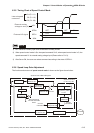
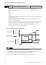
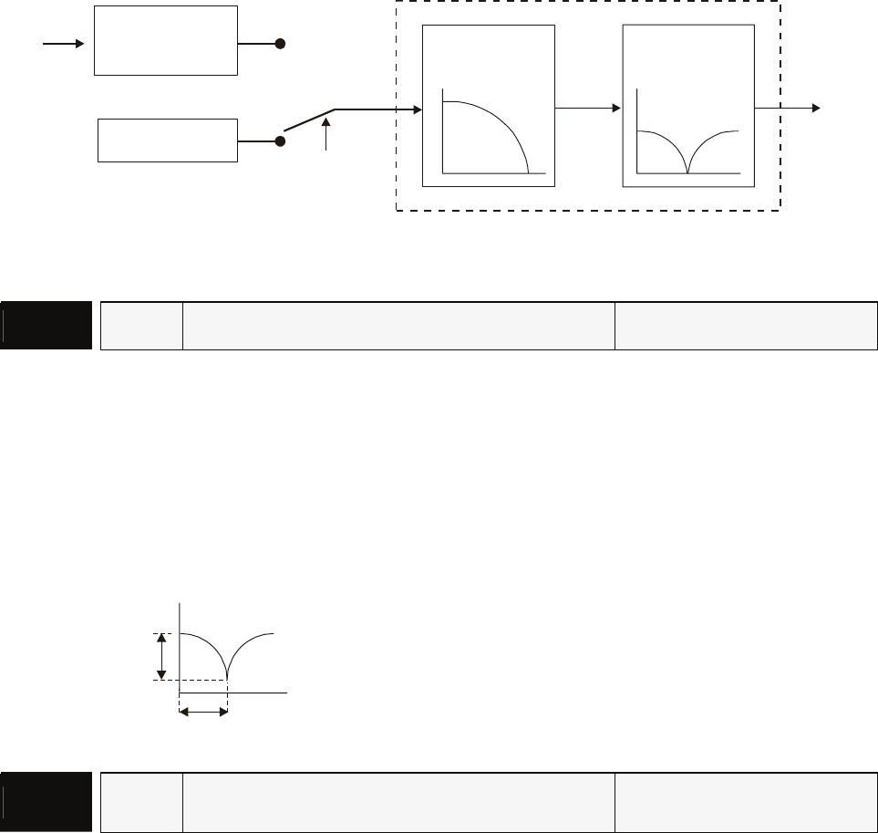
6.3.7 Resonance Suppression
The resonance of mechanical system may occur due to excessive system stiffness or frequency
response. However, this kind of resonance condition can be improved, suppressed, even can be
eliminated by using low-pass filter (parameter P2-25) and notch filter (parameter P2-23, P2-24) without
changing control parameter.
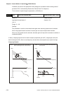
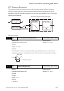
Low-pass
Filter P1-06
Notch Filter
Torque Control
Block Diagram
P1-40
Control Mode
Selection P1-01
Speed Control
Block Diagram
P2-23, P2-24
Resonance Suppression Block Diagram
Relevant parameters:
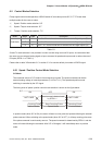
P2 - 23
NCF Notch Filter (Resonance Suppression) Communication Addr.: 0217H
Default: 1000 Related Section:
Applicable Control Mode: P/S/T Section 6.3.7, P2-24
Unit: Hz
Range: 50 ~ 1000
Settings:
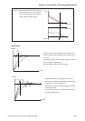
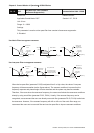
This parameter is used to set resonance frequency of mechanical system. It can be used to
suppress the resonance of mechanical system. If P2-24 is set to 0, this parameter is disabled.
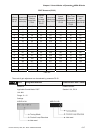
P2-24
P2-23
Gain (db)
Frequency (Hz)
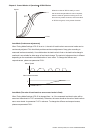
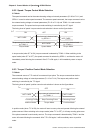
P2 - 24
DPH
Notch Filter Attenuation Rate
(Resonance Suppression)
Communication Addr.: 0218H
Default: 0 Related Section:
Applicable Control Mode: P/S/T Section 6.3.7, P2-23
Unit: dB
Unit: Hz
Range: 0 ~ 32
Settings:
0: Disabled