


Chapter 3 Connections and Wiring|ASDA-B Series
3-16 Revision February 2008, Doc. Name: 2006PDD23000009
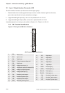
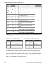
DI
Signal
Assigned
Control Mode
Pin No. Details
(*2)
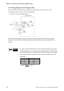
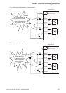
Wiring Diagram
(Refer to 3.3.3)
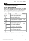
TCM0
TCM1
ALL -
Select the source of torque command:
See Table 3.E.
S-P
Sz , S , P -
Speed / Position mode switching
OFF: Speed, ON: Position
S-T
Sz , S , Tz -
Speed / Torque mode switching
OFF: Speed, ON: Torque
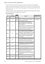
T-P
T , Tz , P -
Torque / Position mode switching
OFF: Torque, ON: Position
EMGS
ALL 14
It should be contact “b” and normally ON or a
fault (ALE13) will display.
CWL
ALL 3
Reverse inhibit limit. It should be contact “b”
and normally ON or a fault (ALE14) will
display.
CCWL
ALL 15
Forward inhibit limit. It should be contact “b”
and normally ON or a fault (ALE15) will
display.
TLLM
P , S -
Torque limit - Reverse operation (Torque limit
function is valid only when P1-02 is enabled)
TRLM
P , S -
Torque limit - Forward operation (Torque limit
function is valid only when P1-02 is enabled)
C8/C9
Footnote *2: The "state" of the input function may be turned ON or OFF as it will be dependant on the
settings of P2-18~P2-20.
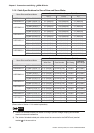
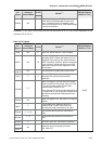
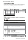
Table 3.D Source of Speed Command Table 3.E Source of Torque Command
SPD1 SPD0 Parameter TCM1 TCM0 Parameter
OFF OFF
S mode: analog input
Sz mode: 0
OFF OFF
T mode: analog input
Tz mode: 0
OFF ON P1-09 OFF ON P1-12
ON OFF P1-10 ON OFF P1-13
ON ON P1-11 ON ON P1-14
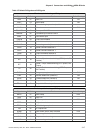
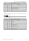
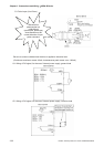
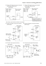
The user-defined DI and DO signals are defined via parameters P2-10 to P2-15 and P2-18 to P2-20.
Please refer to the following Table 3.F for the settings. Although the content of the Table 3.F does not
provide more information than the Table 3.B and Table 3.C above, as each control mode is separated
and listed in different row, it is easy for the users to view and can avoid confusion. However, the Pin
number of each signal can not be displayed in the Table 3.F.