


Chapter 6 Control Modes of Operation|ASDA-B Series
Revision February 2008, Doc. Name: 2006PDD23000009 6-19
Relevant parameters:
P1 - 37
GDR Ratio of Load Inertia to Servo Motor Inertia Communication Addr.: 0125H
Default: 10 Related Section:
Applicable Control Mode: P/S/T P2-31, P2-32, Section 6.3.6
Unit: 0.1times
Range: 0 ~ 2000
Settings:
Ratio of load inertia to servo motor inertia: (J_load /J_motor)
P2 - 04
KVP Proportional Speed Loop Gain Communication Addr.: 0204H
Default: 300 Related Section:
Applicable Control Mode: P/S Section 6.3.6, P2-27
Unit: rad/s
Range: 0 ~ 4095
Settings:
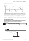
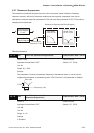
This parameter is used to set the speed loop gain. When the value of proportional speed loop
gain is increased, it can expedite speed loop response. However, if the setting value is over high,
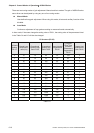
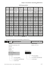
it may generate vibration or noise. In AutoMode, the value of this parameter will be changed in
accordance with the setting value of parameter P2-31 automatically (Please refer Table 6.D &
6.E in Chapter 6).
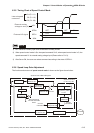
Speed Loop Responsiveness
=( )X[ ]Hz
KVP
2
(1+P1-37/10)
(1+JL/JM)
JM: Motor inertia
JL: Load inertia
P1-37: 0.1 times
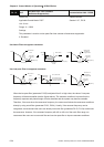
When the setting value of P1-37(no matter it is a measured value or set by
the users) is equal to the actual ratio of load inertia to servo motor inertia,
then the actual responsiveness will be equal to:
= Hz
KVP
2
For example, assume that the desired speed loop responsiveness is 60 Hz =>
KVP (P2-04, Proportional Speed Loop Gain) = 2 × π × 60 = 376 rad/s
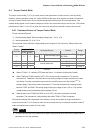
P2 - 06
KVI Speed Integral Compensation Communication Addr.: 0206H
Default: 50 Related Section:
Applicable Control Mode: P/S Section 6.3.6
Unit: rad/s
Range: 0 ~ 1023
Settings:
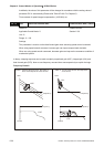
This parameter is used to set the integral time of speed loop. When the value of speed integral
compensation is increased, it can improve the speed response ability and decrease the speed
control deviation. However, if the setting value is over high, it may generate vibration or noise. In