


Chapter 6 Control Modes of Operation|ASDA-B Series
Revision February 2008, Doc. Name: 2006PDD23000009 6-3
Other setting: Reversed
Input pulse interface Max. input pulse frequency
Line driver 500kpps
Open collector 200kpps
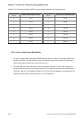
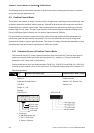
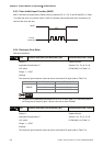
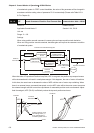
• Logic type
0=Positive Logic 1=Negative Logic
Pulse Type
Forward Reverse Forward Reverse
AB phase pulse
CW + CCW pulse
Pulse + Direction
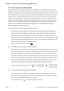
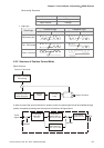
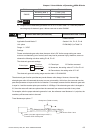
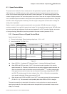
6.2.2 Structure of Position Control Mode
Basic Structure:
Position Command
Position Command
Processing
Position Control
Block Diagram
Speed
Loop
Current
Loop
Output Position
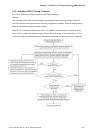
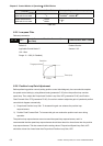
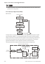
In order to pursue the goal of perfection in position control, the pulse signal should be modified through
position command processing and the structure is shown as the figure below:
INHIBIT
GNUM0
Electronic
gear ratio (1)
P1-44, P1-45
Low-pass
Filter P1-08
Pulse
Signal
Pulse type
selection
P1-00
Electronic
gear ratio (2)
P1-15, P1-45