


Chapter 6 Control Modes of Operation|ASDA-B Series
Revision February 2008, Doc. Name: 2006PDD23000009 6-5
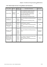
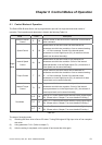
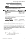
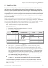
DI Name DI Status Selected Electronic Gear
Not select (Note 1) P1-44, P1-45
0 P1-44, P1-45
GNUM0
1 P1-44, P1-45
NOTE
1) DI signal can be selected by parameter P2-10 to P2-15 and Table 7.A. If uses only need to
use one group of electronic gear, it allows users not to select GNUM0.
P1 - 45▲
GR2 Electronic Gear Ratio (Denominator) Communication Addr.: 012DH
Default: 1 Related Section:
Applicable Control Mode: P Section 6.2.4, P1-15, P1-44
Unit: pulse DI GNUM0(11) in Table 7.A
Range: 1 ~ 32767
Settings:
Please set electronic gear ratio when the servo drive is Off. As the wrong setting can cause
motor to run chaotically (out of control) and it may lead to personnel injury, therefore, ensure to
observe the following rule when setting P1-44, P1-45.
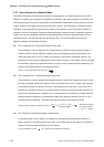
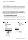
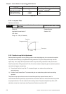
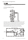
The electronic gear ratio settings:
f1
f2 = f1 x
N
M
N
M
Pulse input
Position
command
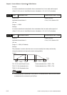
The electronic gear ratio setting range must be within: 1/50<N/M<200.
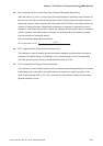
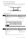
The electronic gear function provides easy travel distance ratio change. However, the over high
electronic gear ratio will command the motor to move not smoothly. At this time, the users can use low-
pass filter parameter to improve this kind of situation. For example, assume that the electronic gear ratio
is equal to 1 and the encoder pulse per revolution is 10000ppr, if the electronic gear ratio is changed to
0.5, then the motor will rotate one pulse when the command from external controller is two pulses.
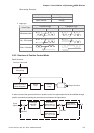
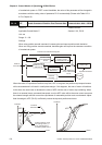
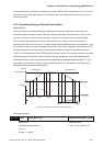
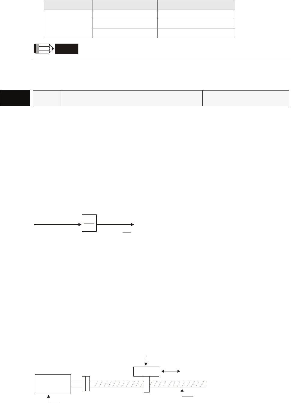
For example, after the proper electronic gear ratio is set, the reference travel distance is 1 μm/pulse, the
machinery will become easier to be used.
Travel distance per pulse = T
Motor (encoder signal output: A/B, Z)
Encoder PPR: 2500 pulse
Ball Screw Pitch: 3mm
Workpiece (Table or Load
)
f1: Pulse input f2: Position command
N: Numerator, the setting value of P1-15 or P1-44
M: Denominator, the setting value of P1-45