


Chapter 7 Servo Parameters|ASDA-B Series
7-48 Revision February 2008, Doc. Name: 2006PDD23000009
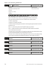
P2 - 29
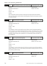
GPE Gain Switching Condition Communication Addr.: 021DH
Default: 10000 Related Section:
Applicable Control Mode: P/S P2-27, P2-28
Unit: pulse, Kpps, rpm
Range: 0 ~ 30000
Settings:
0: Disabled
This parameter is used to set the value of gain switching condition (pulse error, Kpps, rpm)
selected in P2-27. The setting value will be different depending on the different gain switching
condition.
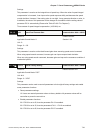
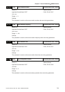
P2 - 30■
INH Auxiliary Function Communication Addr.: 021EH
Default: 0 Related Section: N/A
Applicable Control Mode: P/S/T
Unit: N/A
Range: 0 ~ 5
Settings:
0: Normal operation of Digital Inputs SON, CW, and CCW.
1: Force the servo drive to be Servo On (ignore CW and CCW signal)
2: Ignore CW digital input signal
3: Ignore CCW digital input signal
4: Reserved
5: After setting P2-30 to 5, the setting values of all parameters will lost (not remain in memory) at
power-down. When the parameters data are no more needed, using this mode can allows users
not to save parameters data into memory without damaging the EEPROM.
NOTE
1) Please set P2-30 to 0 during normal operation. The setting value of P2-30 will return to 0
automatically after re-power the servo drive.
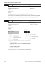
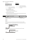
P2 - 31■
AUT1 Auto Stiffness and Responsiveness Level Communication Addr.: 021FH
Default: 6 Related Section:
Applicable Control Mode: P/S/T Section 6.3.6, P1-37, P2-32
Unit: N/A
Range: 0 ~ F
Settings:
This parameter allows user to set the stiffness and responsiveness level automatically.
Users can control the stiffness and responsiveness according to application condition.