


System Management: FRU LEDs
ATCA-9305 User’s Manual 10009109-01
7-18
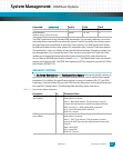
FRU LEDS
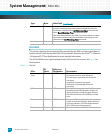
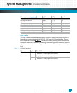
This section describes the front panel LEDs controlled by the IPMC and documents how to
control each LED with the standard FRU LED commands. Reference the PICMG
®
3.0 Revision
2.0 AdvancedTCA
®
Base Specification for more detailed information.
The ATCA-9305 has four Light-Emitting Diodes (LEDs) on the front panel. See
Fig. 2-1 for
their location.
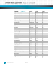
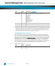
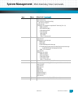
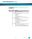
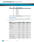
Table 7-11: FRU LEDs
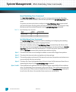
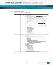
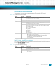
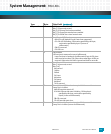
Response Data 8 Present countdown value, lsbyte. The initial countdown value and
present countdown values should match immediately after the
countdown is initialized via a Set Watchdog Timer command and
after a Reset Watchdog Timer has been executed.
Note that internal delays in the IPMC may require software to delay
up to 100 ms before seeing the countdown value change and be
reflected in the Get Watchdog Timer command.
9 Present countdown value, msbyte
LEDs:
ID
(hex):
Reference
Designator: Description:
Hot
Swap
00 CR57 The blue Hot Swap LED displays four states:
On—the board can be safely extracted
Off—the board is operating and not safe for
extraction,
Long blink—insertion is in progress
Short blink—requesting permission for
extraction
OOS 01 CR54 The Out Of Service programmable LED
controlled by the IPMI controller is either red
(North America) or amber (Europe). When lit,
this LED indicates the ATCA-9305 is in a failed
state.
2 02 CR55 The green LED is user defined, but frequently is
used as an In Service indicator. When used as an
In Service indicator, a lit LED indicates that the
ATCA-9305 is functioning properly.
3 03 CR56 The amber LED is user defined.
Type: Byte: Data Field: (continued)