


Management Processor CPLD: MPC8548 PLD Register
10009109-01 ATCA-9305 User’s Manual
5-5
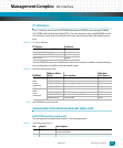
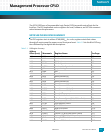
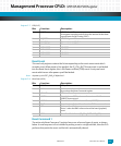
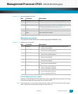
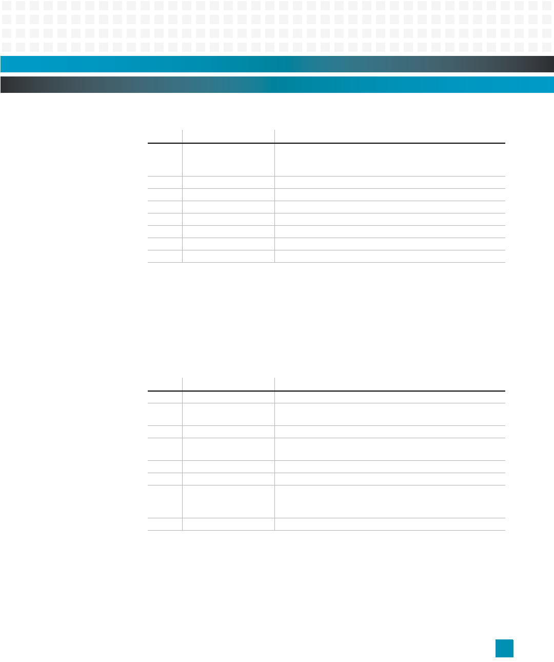
Register 5-7: LED (0x1C)
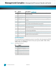
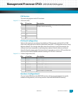
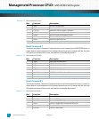
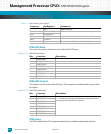
Reset Event
This read-only register contains the bit corresponding to the most recent event which
caused a reset. When power is first applied, the FP_PSH_BUTTN reset event is not latched
into the Reset Event register, this is the Power-on Reset (POR) event. Front panel reset
events which occur after power-up will be latched.
Note: At power-up, the FRST_PWR_UP defaults to 1.
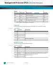
Register 5-8: Reset Event (0x20)
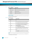
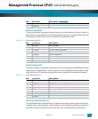
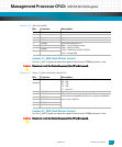
Reset Command 1
The write-only Reset Command 1 register forces one of several types of resets, as shown
below. A reset sequence is first initiated by writing a one to a single valid bit, then the PLD
performs that particular reset, and the bit is automatically cleared.
Bits: Function: Description:
7 PQRED MPC8548 red LED
Lit on power-up and turned off when the monitor finishes boot
up and Power-on Self Testing (POST)
6 PQGREEN MPC8548 green LED
5 SWLEDCLK Ethernet Switch LED Clock
4 SWLEDDAT Ethernet Switch LED Data
3 DEBUGLED3 LED CR22
2 DEBUGLED2 LED CR21
1 DEBUGLED1 LED CR19
0 DEBUGLED0 LED CR18
Bits: Function: Description:
7 RTMPB RTM push button
6 SHR Software Hard Reset Set to 1 when the last reset was caused
by a write to the Reset Command register
5 CPUHRR CPU Hard Reset Request
4 COPSR Set to 1 when a COP header or software-issued Soft Reset
(SRESET) has occurred
3 COPHR Set to 1 when a COP header Hard Reset (HRESET) has occurred
2 PAYR Set to 1 when a Payload Reset from the IPMC has occurred
1SBR Software Board Reset
Set to 1 when the IPMC software issued the board (payload)
reset
0 FPPB Front Panel Push Button (FP_PSH_BUTTN, POR_RST)