Management Processor CPLD: MPC8548 PLD Register
ATCA-9305 User’s Manual 10009109-01
5-8
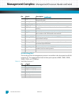
Note: The board powers down and powers back up when the Cavium processors power is back up (bits 0 or 1 are
cleared).
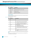
Register 5-14: Reset Command Sticky #1 (0x38)
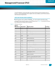
Reset Command Sticky #2
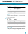
The read/write Reset Command Sticky #2 register forces one of several types of the PHY
reset command, as shown below. A reset sequence is first initiated by writing a one to one
or more bits, then the PLD performs that particular reset. The bit will persist until cleared.
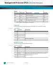
Register 5-15: Reset Command Sticky #2 (0x3C)
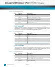
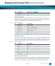
Boot Device Redirection
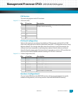
The read/write Boot Device Redirection register (BDRR) allows the user to determine which
of three boot devices the MPC8548 CPU is using as the boot device. Several bits also indi-
cate which device was set as the initial boot device. The Boot Redirected bit is set to a 1
when the current boot device does not match the initial default boot device. This indicates
to the user that the image in the default device was bad, the MPC8548 watch dog timer
expired, and the next device was tried. The boot device redirection order is determined by
IPMC. Reference the “Boot Device Diagram”.
Bits: Function: Description:
7
CAV1C Cavium 1 Complex reset
6
CAV2C Cavium 2 Complex reset
5
SWIC Switch Complex reset
4
CAV1CF Cavium 1 Complex 4MB Flash reset
3
CAV2CF Cavium 2 Complex 4MB Flash reset
2
NANDF NAND Flash reset
1
CAV2RPD Reset and power down the Cavium 2 core
0
CAV1RPD Reset and power down the Cavium 1 core
Bits: Function: Description:
7 TSEC1R TSEC1 Ethernet to front panel PHY Reset
6 TSEC2R TSEC2 Ethernet to switch PHY Reset
5 FPIR FPI Ethernet from switch to front panel PHY Reset
4 BCR Ethernet dual PHY to backplane Base Channel Reset
3 MIP1 SPI to XAUI bridge #1 on Cavium 1
2 MIP2 SPI to XAUI bridge #2 on Cavium 1
1 MIP3 SPI to XAUI bridge #3 on Cavium 2
0 MIP4 SPI to XAUI bridge #4 on Cavium 2


