Management Processor CPLD: MPC8548 PLD Register
10009109-01 ATCA-9305 User’s Manual
5-9
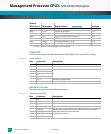
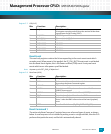
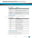
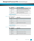
Register 5-16: Boot Device Redirection (0x50)
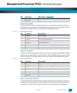
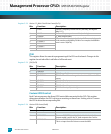
Miscellaneous Control
This register includes two bits for manually toggling the MPC8548 I
2
C bus.
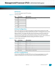
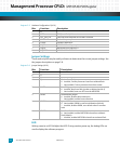
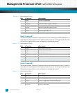
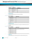
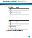
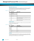
Register 5-17: Miscellaneous Control (0x54)
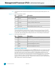
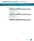
Low Frequency Timer 1 and 2
Registers LFTR1 (0x58) and LFTR2 (0x5C) are timers. They determine how many 50 μs inter-
vals you want before the next interrupt on Cavium GPIO5.
Note: Unless the frequency is set to 0, there is always one 50 μs interval. This is the reason for the register setting
being 1 less than an even hundred, for example 199 rather than 200.
Bits: Function: Description:
7 SELFRS Self Refresh Started
6 BOOTSEL1 IPMC successful boot indication (BOARD_BOOTED)
5 reserved
4 BSJ Boot from Socket Jumper A shunt on J9 [1:2] selects the
512KB socketed ROM as the boot device, see Fig. 2-6.
3 NFBS Nand Flash Busy Signal
2BDS Active boot device is socket
1 BDF1 Active boot device is flash 2
0 BDF0 Active boot device is flash 1
Bits: Function: Description:
7 P33WP 0 Write Protect disabled (default until the monitor boots)
1Write Protect enabled
6 SROM1WP 0 Write Protect disabled
1 Write Protect enabled (default)
5 SROM0WP 0 Write Protect disabled
1 Write Protect enabled (default)
4 FLASH1WP 0 Write Protect disabled (default until the monitor boots)
1Write Protect enabled
3 FLASH0WP 0 Write Protect disabled (default until the monitor boots)
1Write Protect enabled
2 NANDWP 0 Write Protect disabled
1 Write Protect enabled (default)
1I2CSDA I
2
C Data line
0 Drive a 0 onto the I2C SDA line
1 Drive a 1 onto the I2C SDA line
0I2CSCL
I
2
C Clock line
0Drive a 0 onto the I2C SCL line
1Drive a 1 onto the I2C SCL line


