Setup: ATCA-9305 Setup
ATCA-9305 User’s Manual 10009109-01
2-8
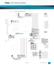
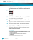
Configuration Header
There are a total of seven jumper pairs on J9 (pins 11-14 are spare posts). See figure Fig. 2-2
for the jumper location on the ATCA-9305. Also reference the “Jumper Settings (0x18)” reg-
ister.
Figure 2-6: Configuration Header, J9
BT SKT: A shunt on pins 1-2 selects the 512 KB socketed ROM as the boot device for the MPC8548.
IG SROM: If the serial ROM configuration jumper is installed (pins 3-4), the ATCA-9305 will not try to
configure (IGNORE_SROM*) from the MPC8548 serial ROM.
REDIR EN: A shunt installed on pins 5-6 disables the boot redirection, see page 7-41 for more informa-
tion.
BOOT: A shunt on pins 7-8 causes both Cavium CN5860s to boot from their local bus and not boot
over PCI.
STAND: A shunt on pins 9-10, IPMC stand alone mode, allows the board to boot without manage-
ment control.
PROG: Installing a shunt on pins 11-12 puts the IPMC controller into programming mode. This is
only used in the factory to configure the IPMC.
BT FLASH: If BOOT shunt is installed (booting from local bus), this shunt determines whether the boot
is from local flash or socket. When this BT FLASH shunt is installed, the ATCA-9305 boots
from flash. Otherwise, it boots from the socket.
ATCA-9305 SETUP
You need the following items to set up and check the operation of the Emerson ATCA-9305:
ATCA chassis and power supply
MPC8548 Console cable for EIA-232 port, Emerson part # C0007662-00
Computer terminal
Save the antistatic bag and box for future shipping or storage.
13 11 9 7 5 3 1
14 12 10 8 6 4 2
BT SKT
IG ROM
REDIR EN
BOOT
STAND
PROG
BT FLASH


