Ethernet Interface: MPC8548 Management Processor Ethernet
10009109-01 ATCA-9305 User’s Manual
6-3
VLAN Setup
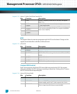
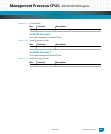
The default VLAN configuration is defined in Tab le 6 - 2. See page 9-25 for the monitor vlan
command.
Table 6-2: VLAN Configuration
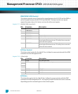
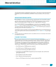
MPC8548 MANAGEMENT PROCESSOR ETHERNET ADDRESS
The Ethernet address for your board is a unique identifier on a network. The address con-
sists of 48 bits (MAC [47:0]) divided into two equal parts. The upper 24 bits define a unique
identifier that has been assigned to Emerson Network Power, Embedded Computing by
IEEE. The lower 24 bits are defined by Emerson for identification of each of our products.
The Ethernet address for the ATCA-9305 is a binary number referenced as 12 hexadecimal
digits separated into pairs, with each pair representing eight bits. The address assigned to
the ATCA-9305 has the following form:
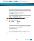
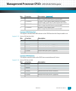
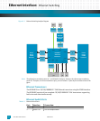
3 SGMII 1 GB Switch PHY to front panel RJ45 connector
4 SGMII 1 GB Management processor PHYs to front panel RJ45 connector
5 XAUI 10 GB Stratix II GX bridge 2
6 XAUI 10 GB Stratix II GX bridge 1
7 XAUI 10 GB Back plane Fabric
8 XAUI 10 GB Back plane Fabric
9— not used
10 — not used
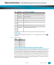
11 XAUI 10 GB BCM56802 to J30 to optional RTM
12
13 XAUI 10 GB Stratix II GX bridge 3
14 XAUI 10 GB Stratix II GX bridge 4
15 XAUI 10 GB BCM56802 to J31 to optional RTM
16
17
18
VLAN: Ports:
11, 3, 4
26, 7
38, 13
45, 11
512, 14
Port: Interface: Connection: (continued)


