System Management: E-Keying
10009109-01 ATCA-9305 User’s Manual
7-51
E-KEYING
This section details the interfaces governed by E-keying and the protocols they support.
Specifically, this includes the interfaces implemented by this product and the E-keying defi-
nition that corresponds to each interface.
The IPMC supports E-keying for the ATCA-9305 per PICMG® ATCA 3.0, Revision 2.0 and
PICMG 3.1, Revision 1.0 specifications The E-keying information is stored in the ATCA Point-
to-Point Connectivity Record located in the Multi-Record area of the FRU Inventory Informa-
tion (see page 7-50). The ATCA Point-to-Point Connectivity Record contains a Channel
Descriptor list, where each Link Descriptor details one type of point-to-point protocol sup-
ported by the referenced channels.
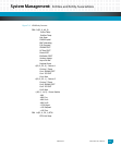
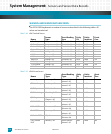
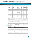
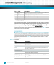
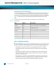
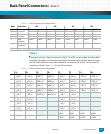
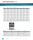
The ATCA channel descriptors define the ATCA channels implemented on a module. Each
channel has an arbitrary set of up to four ports. Channel descriptors map physical ports to
logical entities known as lanes, see
Ta bl e 7- 50 .
Note: Certain Ethernet core switch and fat pipe switch module GbE switch ports are disabled due to lack of e-keying
support in the monitor.
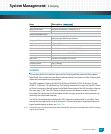
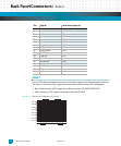
Board Serial Number Variable, formatted as “730-XXXX”
Board Part Number Variable, formatted as “10XXXXXX-YY-Z”
FRU File ID Variable, for example: “fru-info.inf”
Product Information Area
Version Version number of the Product Information Area data structure
defined by the IPMI FRU specification
Language Code 0x01 = English
Manufacturer Name “Emerson”
Product Name “ATCA-9305”
Product Part/Model Number Variable, formatted as “10XXXXXX-YY-Z”
Product Version Not used, same information is provided by the part number
Product Serial Number Variable, formatted as “730-XXXX”
Asset Tag Not Used
FRU File ID Variable, for example: “fru-info.inf”
MultiRecord Area
E-Keying records See “E-Keying”
Maximum Internal Current “12.5 Amps”
Item: Description: (continued)


