


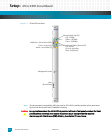

Setup: ATCA-9305 Circuit Board
10009109-01 ATCA-9305 User’s Manual
2-7
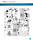
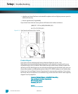
Connectors
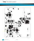
The ATCA-9305 circuit board has various connectors and headers (see the figures beginning
on page 2-3), summarized as follows:
J1: This 14-pin JTAG header is used for debugging CN5860 processor 2. See
Ta bl e 3- 7.
J3-J6: These 240-pin sockets are installed for the CN5860 processor 1 DDR2 SDRAM memory.
J9: This 14-pin configuration header allows selection of boot device, and MPC8548 configura-
tion for the configuration SROM. See
Fig.2-6.
J11-J14: These 240-pin sockets are installed for the CN5860 processor 2 DDR2 SDRAM memory.
J15: This 14-pin JTAG header is used for debugging CN5860 processor 1. See
Ta bl e 3- 7.
J23: The 80-pin Zone 2 connector provides 1 GB and 10 GB Ethernet access to the backplane, see
Ta bl e 8 - 2.
J30-J31: The 80-pin Zone 3 connectors route PCIe and XAUI (10G) to the optional RTM. See
Ta bl e 8 - 3
and
Ta bl e 8 - 4 for pin assignments.
J33: The 24-pin Zone 3 connector routes the reset, Hot Swap, MPC8548 console, power, and
IPMC I
2
C to the optional RTM, see Ta bl e 8- 5.
JP1: This is the 10-pin programming header for the IPMP, CPLD, and SPI 10G (1-4) devices, see
Ta bl e 7 - 51 .
P1: This 14-pin RJ45 connector with LEDs routes the Three-speed Ethernet Controller (TSEC1)
between the MPC8548 and the front panel. See
Ta bl e 6- 4 for pin assignments.
P2: This 16-pin JTAG debug header accesses the MPC8548 processor, see
Ta bl e 4 - 7.
P3: This 14-pin RJ45 connector with LEDs routes Ethernet (FP1) between the switch and the
front panel, see
Ta bl e 6 - 4 for pin assignments.
P4: The 5-pin vertical mini-B USB provides the IPMP EIA-232 console debug, see
Ta bl e 7 - 52 .
P5, P6: These 5-pin vertical mini-B USBs are the CN5860 console and for factory debug use only.
P7: This 5-pin mini-B USB is the console serial port for the MPC8548 management processor,
see
Ta bl e 4 - 8.
P10: The 30-pin Zone 1 connector routes IPMB to the backplane, see
Ta bl e 8 - 1.