


Management Complex: I2C Interface
10009109-01 ATCA-9305 User’s Manual
4-9
I
2
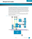
C INTERFACE
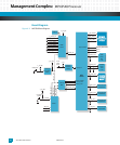
The I
2
C interface consists of the MPC8548 initialization EEPROM, user (storage) NVRAM,
SO-CDIMM, and the Real-time Clock (RTC). The two Atmel two-wire serial EEPROMs on the
I
2
C interface consist of the Serial Clock (SCL) input and the Serial Data (SDA) bidirectional
lines.
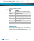
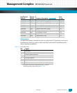
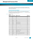
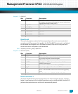
Table 4-5: I
2
C Device Addresses
The two EEPROMs store non-volatile information such as board, monitor, and operating sys-
tem configurations as well as customer specific items.
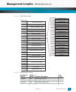
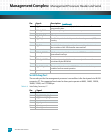
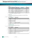
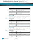
Table 4-6: MPC8548 NVRAM Memory Map
Note: Both EEPROMs are write-protected.
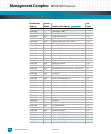
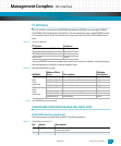
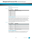
MANAGEMENT PROCESSOR HEADER AND SERIAL PORT
JTAG/COP Interface (optional)
The management complex uses header P2 for debug purposes.
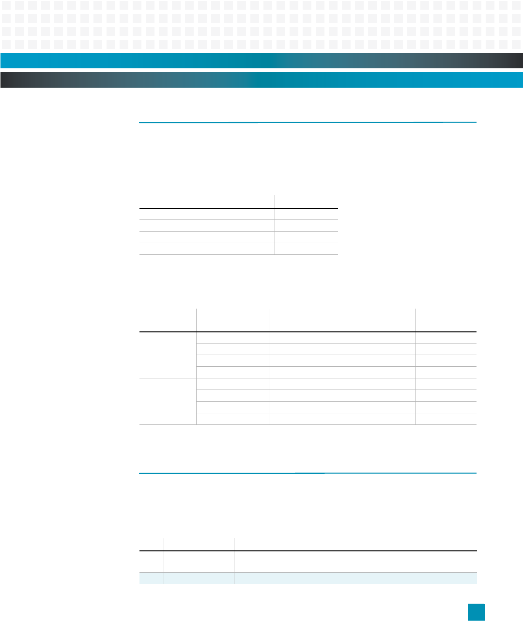
Table 4-7: Serial Debug Connector, P2
I
2
C Device: Address:
MPC8548 Initialization (EEPROM-2) 0xA0
User NVRAM (EEPROM-1) 0xA2
DDR2 SDRAM (SO-CDIMM) 0xA4
M41T00 RTC 0xD0
EEPROM:
Address Offset
(hex): Description:
Window
Size (bytes)
EEPROM-1
0xA2
(write
protected)
0x1FF0-0x1FFF Boot verify secondary area (monitor) 16
0x1FE0-0x1FEF Boot verify primary area (monitor) 16
0x1EE0-0x1FDF Operating system parameters (monitor) 256
0x0000-x1EDF User defined 7903
EEPROM-2
0xA0
(write
protected)
0x0900-0x1FFF Emerson reserved area 5887
0x0800-0x08FF Miscellaneous 256
0x07F0-0x07FF Power-on Self-test (POST) 16
0x0000-0x07EF User defined 2032
Pin: Signal: Description:
1 PQ_TDO Test Data Output is the serial data output as well as test and
programming data.
2 no connect —