


Chapter 5 Internal Components Access 5-3
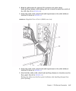
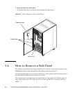
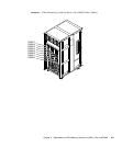
5.3 How to Remove a Door
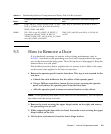
If it is absolutely necessary to remove a door during maintenance, refer to
FIGURE 5-2 and remove the grounding wire from the fixing bracket at the upper
part of the door and the hinge parts. Then, lift the door to disengage it. Keep the
removed door in a safe place.
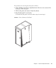
The detailed procedure below explains how to remove a door. Most of the steps
are the same when applied to the front or rear door.
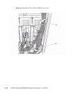
1. Remove the operator panel from the front door. This step is not required for the
rear door.
a. Unhook the cable holders to free the cables of the operator panel.
b. Using a Phillips screwdriver, loosen the two screws securing the operator
panel, and remove the operator panel from the front door.
c. Affix the operator panel to some convenient location on the cabinet.
Note – If the operator panel need not be removed for maintenance, you can remove
the cables from the sensor unit side.
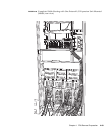
2. Remove the screw securing the upper hinge bracket on the right, and remove
the grounding wire as well.
3. While supporting the door with one hand, loosen the screw securing the upper
hinge bracket on the left.
4. Lift the door, and remove it from the lower hinge bracket.
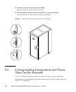
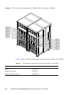
TABLE 5-1 Relationship Between Components and Doors That Can Be Accessed
Model
Component (abbreviation) maintained through front
door
Component (abbreviation) maintained through rear
door
M8000 CMU, XSCFU, TAPEU, DVDU, DDC_A, PSU,
FAN_A (3-FAN), FAN_B (2-FAN #0 and #1),
OPNL, SNSU, and RDPF
IOU, ACS_A, and FAN_B (2-FAN #2 to #7)
M9000 PSU, IOU (even ID), XSCFU_B, XSCFU_C
(expansion cabinet), CLKU_B, XBU_B,
TAPEU, DVDU, PSU, ACS_B, FAN_A (3-FAN
#0 to #3), OPNL, and SNSU
CMU, IOU (odd ID), and FAN_A (3-FAN #4
to #15)