


8-16 SPARC Enterprise M8000/M9000 Servers Service Manual • June 2010
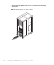
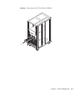
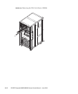
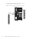
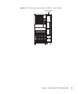
9. While grasping the handle of the FAN unit to be replaced, pull it out slowly
from the slot.
10. Place the removed FAN unit on an antistatic mat.
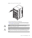
11. Mount the replacement FAN unit by following the removal instructions in
Step 8 and Step 9 in reverse order. Align the FAN unit with the slot guides,
insert it carefully, and secure it firmly.
Caution – Do not forcibly push the FAN unit when inserting it, even if it is not
moving smoothly. If the FAN unit is forcibly inserted despite the presence of any
obstruction in a slot or any problem with a connector pin, serious damage may
result.
12. Switch on all main line switches for the AC section (ACS) in the power supply
system.
13. Confirm that the XSCF STANDBY LED (green) on the operator panel remains
lit. If it is blinking, wait until it remains lit.
14. Start (turn on power) all domains together. Take either of the following two
actions:
■ Press and hold down (for less than four seconds) the POWER switch on the
operator panel.
■ From a console that is connected to XSCF, execute the poweron -a command
of XSCF.
The power to all the domains is turned on, and then the power-on self test (POST)
is executed. When ok prompt displayed on the console of relevant domain, POST
is completed.
For details of the power-on operation, see Section 4.4.2, “Powering the Server On”
on page 4-19, and the SPARC Enterprise M3000/M4000/M5000/M8000/M9000
Servers XSCF User’s Guide.
15. Confirm that the replacement components are normal by using the
showhardconf or showstatus command of XSCF.
Unless "*" is displayed for the replacement FAN, it is operating normally.
For details of the showhardconf command and showstatus command, see the
SPARC Enterprise M3000/M4000/M5000/M8000/M9000 Servers XSCF User’s Guide,
the SPARC Enterprise M3000/M4000/M5000/M8000/M9000 Servers XSCF Reference
Manual, or the man page.
Note – The showstatus command displays information on degraded components.