


Chapter 6 Replacement of CPU/Memory Board Unit (CMU), CPU, and DIMM 6-27
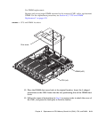
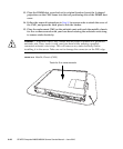
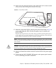
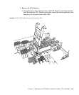
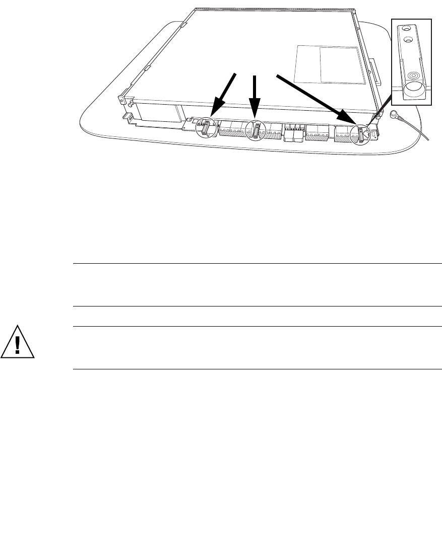
16. Touch each of the designated points on the guide blocks for 5 or more seconds
with your bare hand wearing the antistatic wrist strap.
FIGURE 6-11 Guide Block (CMU)
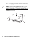
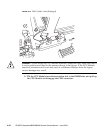
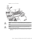
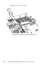
17. Mount the replacement CMU by following the removal instructions in Step 8 in
reverse order. Align the CMU with the slot guides, insert it carefully, and
secure it firmly.
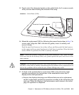
Push the eject/lock levers as far as they will go, and then push the knob screws
on the upper and lower eject/lock levers to lock them in position. When the knob
screws remain in position, the CMU is securely mounted.
Note – Mount the dummy (filler) unit in the same manner as CMU. Since the same
levers are used on the dummy (filler) unit, please operate the eject/lock levers in the
same manner.
Caution – Do not forcibly push the CMU when inserting it, even if it is not moving
smoothly. If the CMU is forcibly inserted despite the presence of any obstruction in a
slot or any problem with a connector pin, serious damage may result.
18. Switch on all main line switches for the AC section (ACS) in the power supply
system.
19. Confirm that the XSCF STANDBY LED (green) on the operator panel remains
lit. If it is blinking, wait until it remains lit.
Touch for 5 or more seconds.