


6-1
CHAPTER
6
Replacement of CPU/Memory
Board Unit (CMU), CPU, and DIMM
This chapter explains the procedures for replacing the CPU/Memory board unit
(CMU) and the CPUs and DIMMs mounted in the CMU. It covers the following:
■ Section 6.1, “Overview of the CMU” on page 6-1
■ Section 6.3, “Active Replacement and Hot Replacement” on page 6-12
■ Section 6.4, “Cold Replacement” on page 6-23
■ Section 6.5, “CPU and DIMM Replacement” on page 6-29
There are three methods for replacing a CMU: active replacement, hot replacement,
and cold replacement. For the definition of each method, see Section 4.1, “Types of
Replacement Procedures” on page 4-2.
The section on swapping methods explains how to replace a CMU. For details on
swapping only a CPU or DIMM, see also Section 6.5, “CPU and DIMM
Replacement” on page 6-29.
Section 6.5, “CPU and DIMM Replacement” on page 6-29 also covers the memory
installation conditions when adding more DIMMs.
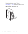
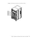
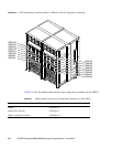
6.1 Overview of the CMU
This section provides an overview of the CMU and shows CMU mounting locations.
Each CMU has 4 CPU slots and 32 DIMM slots. When a CMU is replaced, the
mounted parts (CPUs and DIMMs) must be remounted in the new CMU. These
mounted parts must be remounted at the same locations in the new CMU as their
original pre-swap mounting locations. In addition, the flash memory of each CMU
(FMEM) stores the POST/OpenBoot™ PROM firmware. The firmware is
automatically restored to its pre-swap version.