Chapter 17 Crossbar Unit Replacement 17-5
Caution – If the dual power feed option is installed, switch off the main line
switches for both power supply units.
Caution – After stopping all the domains, be sure to switch off the main line
switches in the power supply system to completely shut off the supply of power.
6. Connect the clip of the antistatic wrist strap and of the antistatic mat to the
server grounding port. See Section 1.4, “Antistatic Precautions” on page 1-6.
7. Ensure that the metallic underside of the wrist strap is in direct contact with
your skin. The wrist strap should be snug around the wrist so that it does not
rotate. See Section 1.4, “Antistatic Precautions” on page 1-6.
Caution – Before handling FRUs, be sure to connect the clip of the antistatic wrist
strap and of the antistatic mat to the server grounding port, and attach the band of
the wrist strap to one of your wrists. Place the FRUs on the grounded antistatic mat.
Failure to take these antistatic measures might result in serious damage.
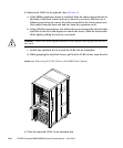
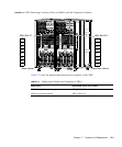
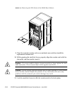
8. Remove the XBU to be replaced. (See
FIGURE 17-3)
a. If the M9000 expansion cabinet is installed, slide both the top and bottom
cable support brackets at the front of the replacement target crossbar unit up
or down by two holes, remove the clock cables connecting the crossbar units
in the base and the expansion cabinets, and then use a flathead screwdriver
to remove the data cables.
b. Using a Phillips screwdriver, turn the knob screws securing the left and right
eject/lock levers 90 to 180 degrees to unlock the levers. (Turn the knob screw
while lightly pulling the lever by one hand.)
c. Unlock the eject/lock levers to pull the XBU off the backplane.
d. While grasping the eject/lock levers, pull out the XBU slowly from the slot.
Caution – Do not hang or yank the cable. Especially do not while the one side is
connected.
Caution – Tighten or remove the cable screws evenly on both sides.


