2-2 SPARC Enterprise M8000/M9000 Servers Service Manual • June 2010
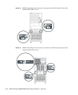
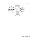
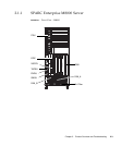
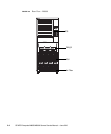
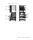
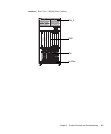
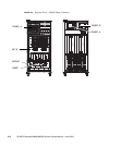
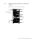
The front and rear views of FIGURE 2-1, FIGURE 2-2, FIGURE 2-4, FIGURE 2-5, FIGURE 2-7,
and
FIGURE 2-8 include names and abbreviations for field-replaceable units (FRUs).
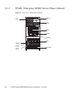
Components that are mounted inside the system are shown
FIGURE 2-3, FIGURE 2-6,
and
FIGURE 2-9. The abbreviations are used in messages and the like. If multiple
FRUs of the same type are mounted, the number sign # and a sequential number is
added to their names to distinguish them from one another. Owing to the reduced
scale, certain components (FRUs) are difficult to show in the figures. Accordingly,
the layout of these components as viewed from one side is indicated in the table
connected by a lead line to the component location.


