Chapter 20 Backplane Replacement 20-7
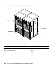
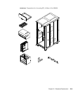
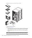
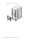
Perform the following operations from the rear of the unit (See FIGURE 20-4):
a. Remove the grounding wire on one side at the top of the rear door so that the
door can be opened at least 180 degrees.
b. Remove all FAN units on the I/O unit. (See Chapter 8) Mount the fixing
brackets of the FAN unit at their original locations, and secure them
temporarily.
c. Using a Phillips screwdriver, loosen the two thumb screws securing the duct
on the fan shelf. While grasping the handle, remove the duct.
d. Using a Phillips screwdriver, loosen the four thumb screws on the left and
right sides of the fan shelf.
e. While grasping the handle of the fan shelf, pull it out partially. Move your
hands to the indentations on the both sides of the fan shelf, and then pull
out the fan shelf carefully from the cabinet.
f. Remove all mounted I/O units (IOUs) including filler panels. (See Chapter 7)
g. Using a Phillips screwdriver, loosen the two knob screws on both sides of
the IOU shelf and the two screws on the innermost part of the shelf.
h. While grasping the frame of the IOU shelf, carefully pull out the IOU shelf
partially, then switch to grasping the shelf by the indentations on its side,
and remove it from the cabinet.
i. Using a Phillips screwdriver, loosen the two retaining screws of the L-
shaped box on the left side in the cabinet to remove the box.
j. Using a Phillips screwdriver, loosen the retaining screws on the left and
right sides to remove the horizontal IOU-fan connector panel on the far side
in the cabinet. Disconnect the cables as well. Also remove the connector on
the right side.


