Chapter 20 Backplane Replacement 20-11
c. Arrange the cables so that the connectors do not get caught in anything
while the BP is being removed.
d. Using a Phillips screwdriver, loosen the eight thumb screws securing the BP.
The BP does not fall because it is suspended from the two guide rails inside the
upper part of the cabinet.
e. While grasping the two handles of the BP, remove the BP by moving it
carefully along the guide rails.
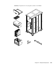
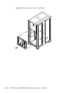
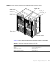
■ M9000 (See FIGURE 20-7):
a. Using a torque wrench, remove the four hexagonal bolts on the bus bar of
the BP.
b. With the connectors unlocked, disconnect all cables from the BP.
Note – Be sure to press both lock release buttons inward and pull the connector
when removing the SAS cables (lock release buttons of the connector are yellow).
c. Arrange the cables so that the connectors do not get caught on anything
while the BP is being removed.
d. Using a Phillips screwdriver, loosen the six thumb screws securing the BP.
The BP does not fall because it is mounted on the two guide rails inside the
lower part of the cabinet.
e. While grasping the upper parts of the BP frame, lower it toward you, and
place it horizontally on the guide rails.
f. While grasping the left and right sides of the BP frame, remove the BP by
moving it carefully along the guide rails.


